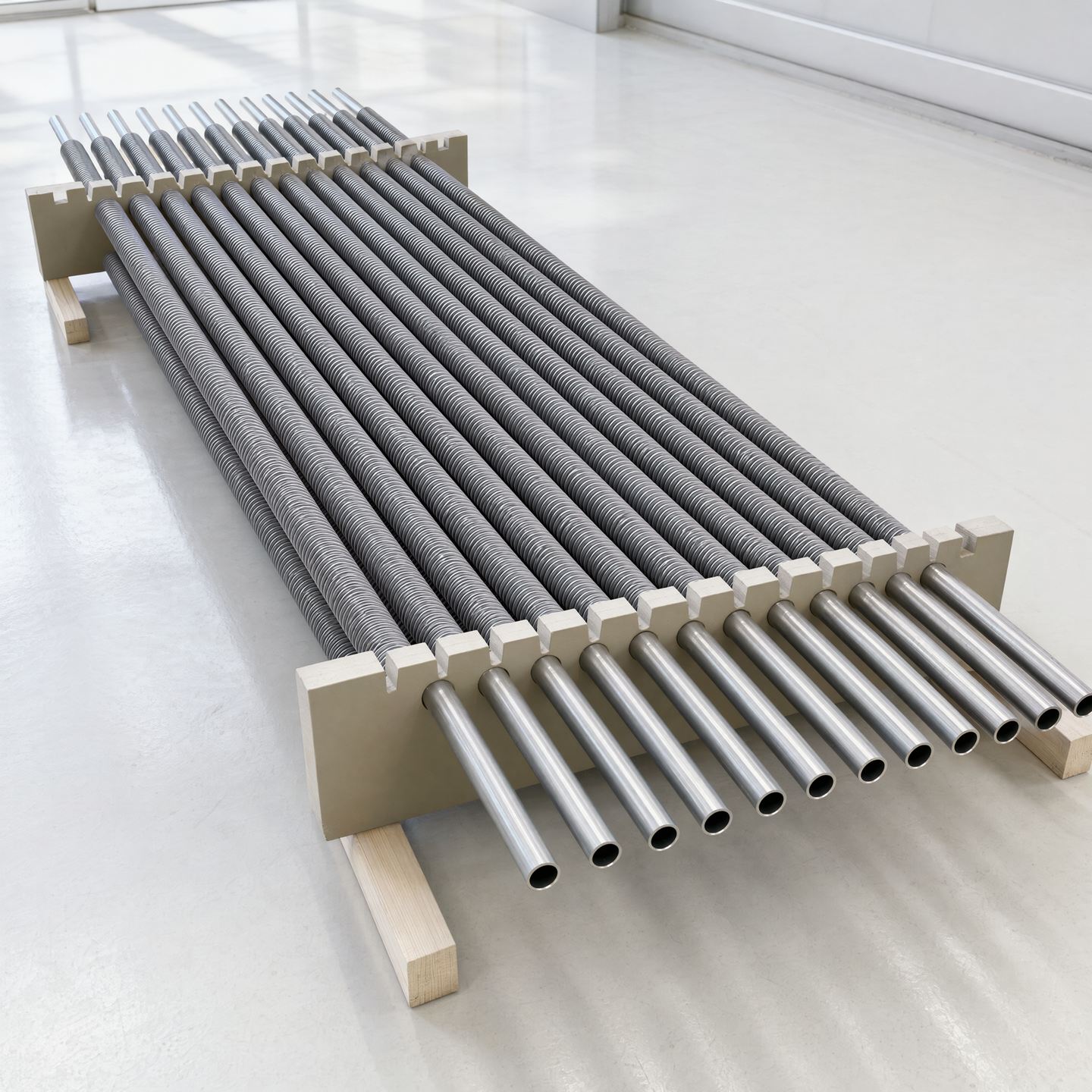
Handling decisions depend on the actual bundle condition: loose tubes, ordered bank, connected module or complete assembly. The customer defines the required equipment; the manufacturer proposes a movement and protection method suited to the agreed fabrication state.
Define pick points before movement is required
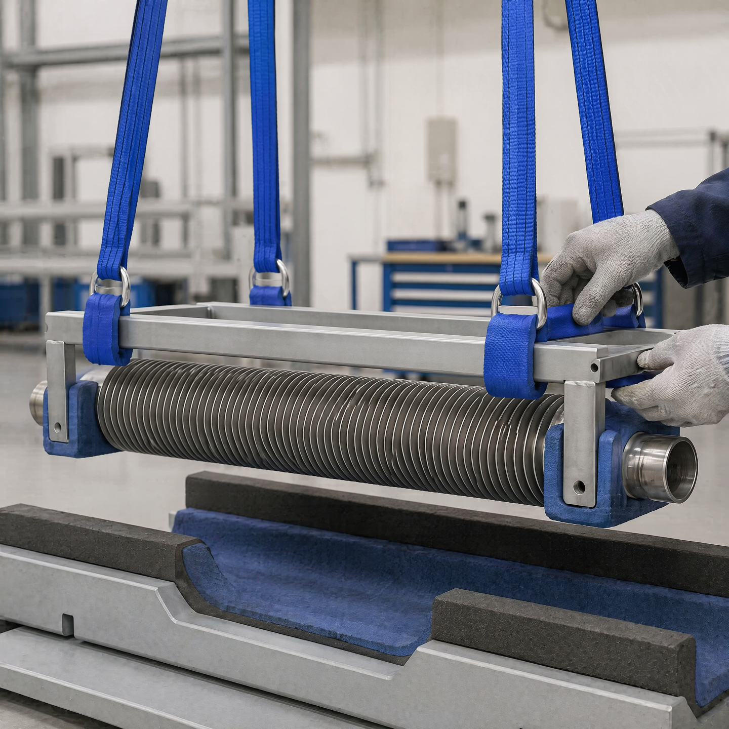
Temporary supports and pick points should keep loads away from exposed fins and prevent the tube order from shifting. The route also needs space for the lifting or transfer equipment that will be available at each stage.
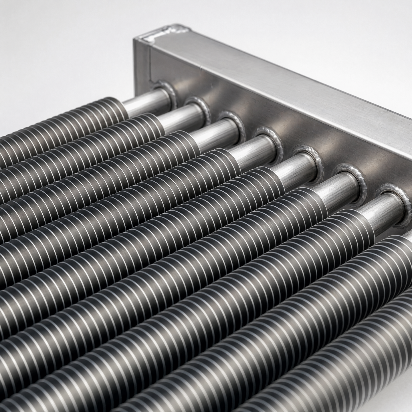
Protect fins, bare ends and finished interfaces differently
Fins need broad contact and separation from hard edges. Bare tube ends and open connections need contamination control. Flange faces and finished interfaces need protection that remains compatible with later fit-up and inspection.
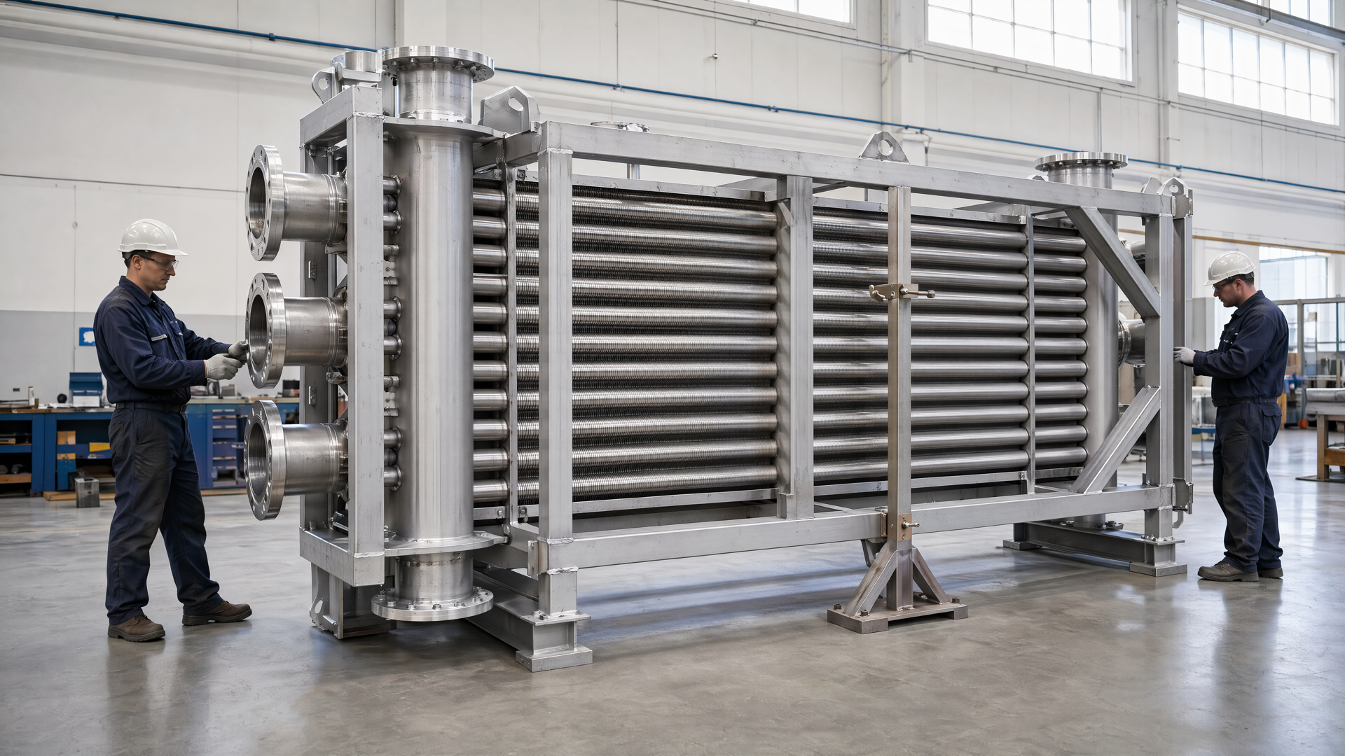
Plan the route into the frame
Before the bundle is moved, confirm which side of the frame remains open, where temporary support can sit, how ordering marks remain visible and when connections become rigid. A route that depends on unavailable access should be revised before fabrication.
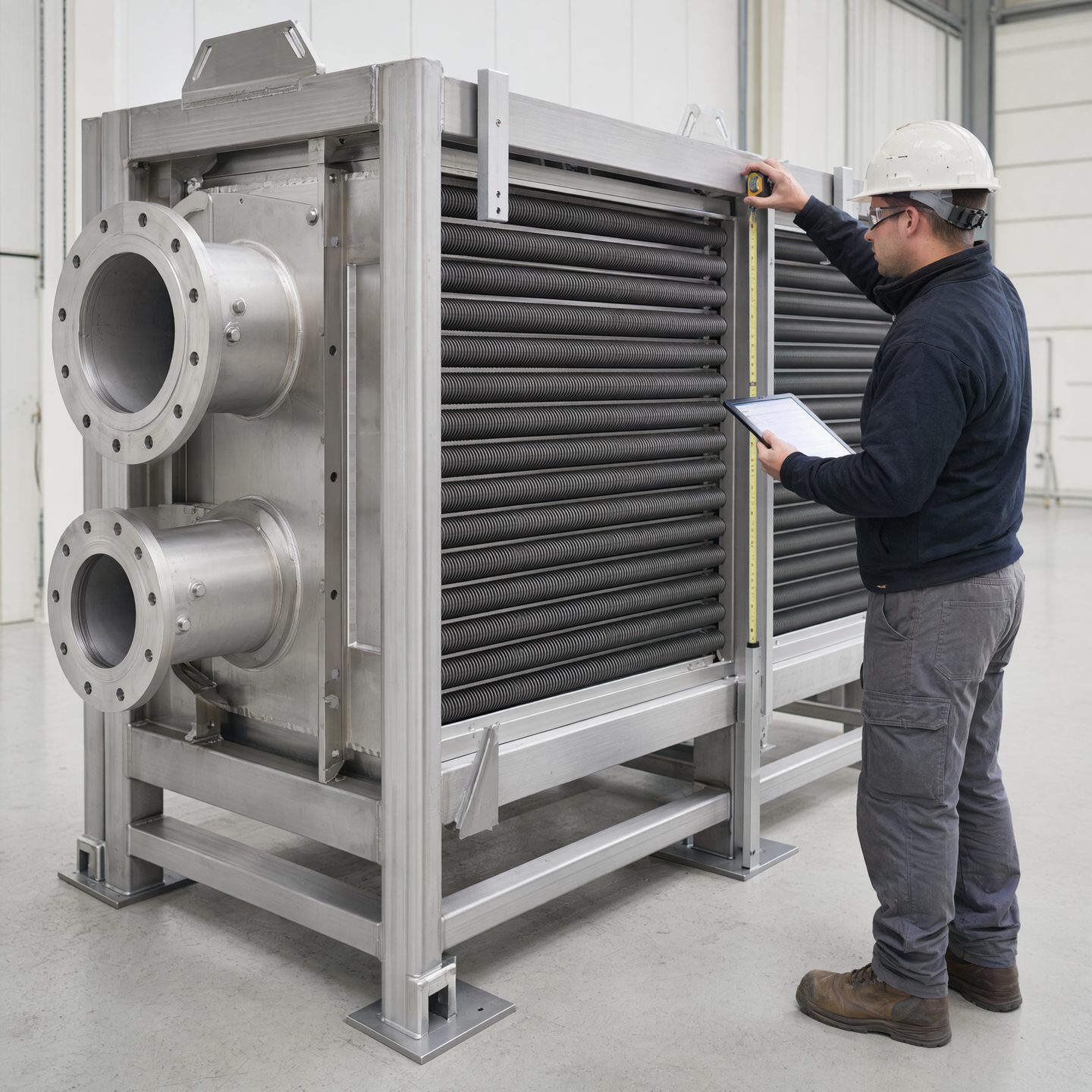
Handling checklist
- Bundle state at each movement
- Permitted pick and support points
- Fin-contact restrictions
- Bare-end and flange-face protection
- Ordering and orientation marks
- Open side of the frame
- Temporary support removal point
- Final delivery-state restraint
Handling-state atlas
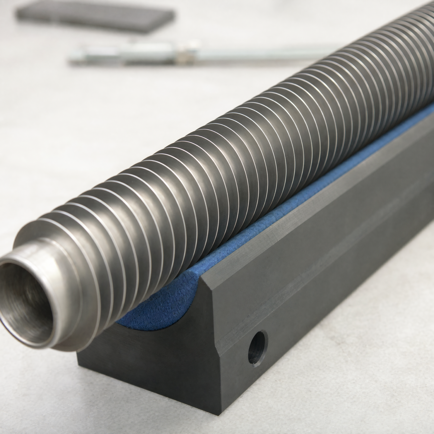
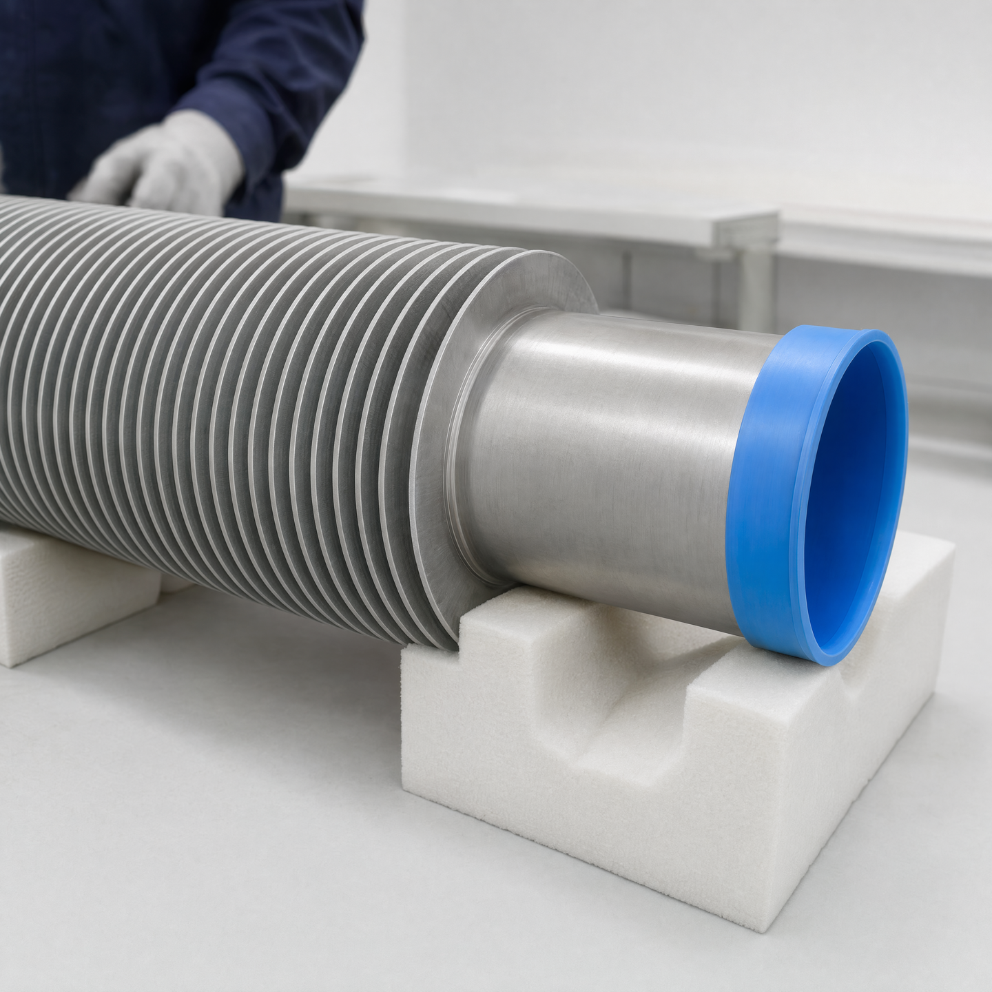
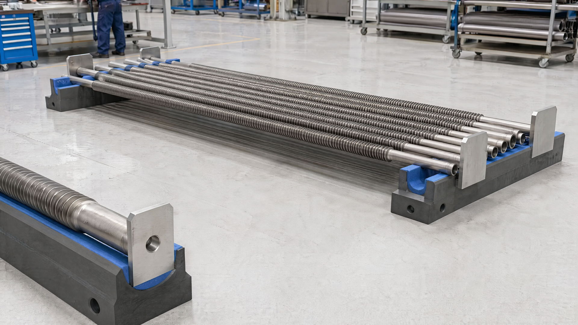
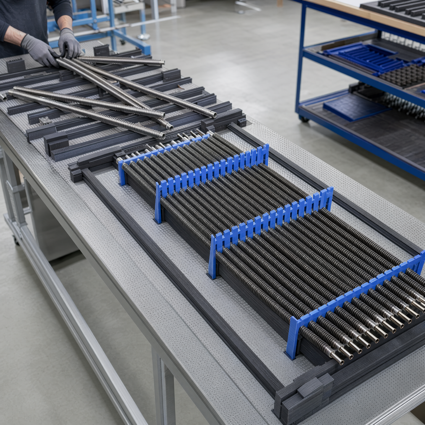
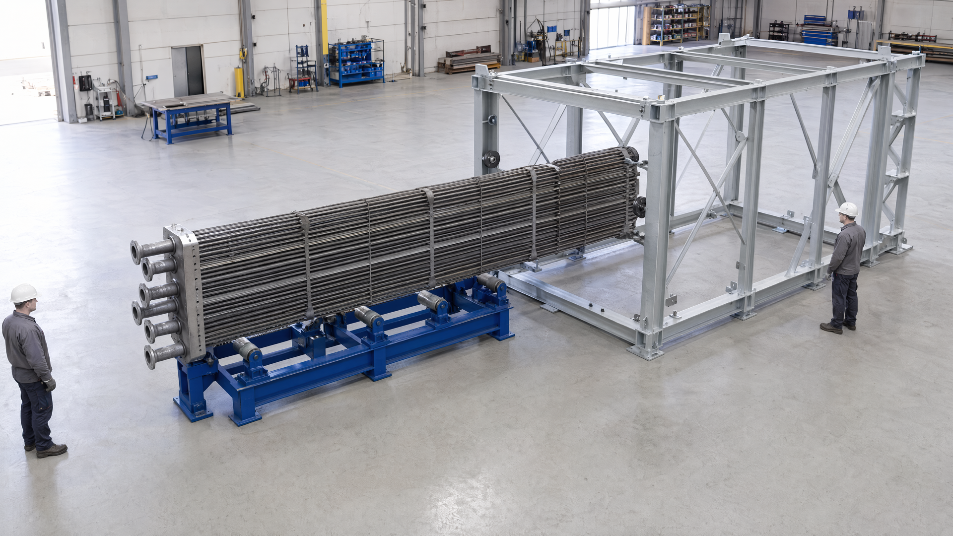
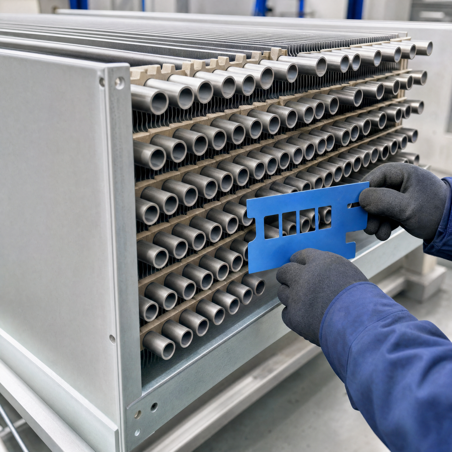
The handling route should name the component state, the rigid load path and the vulnerable surfaces at every movement. These illustrations are references for that conversation; they do not define a standard lifting fixture or guarantee a shipping outcome.
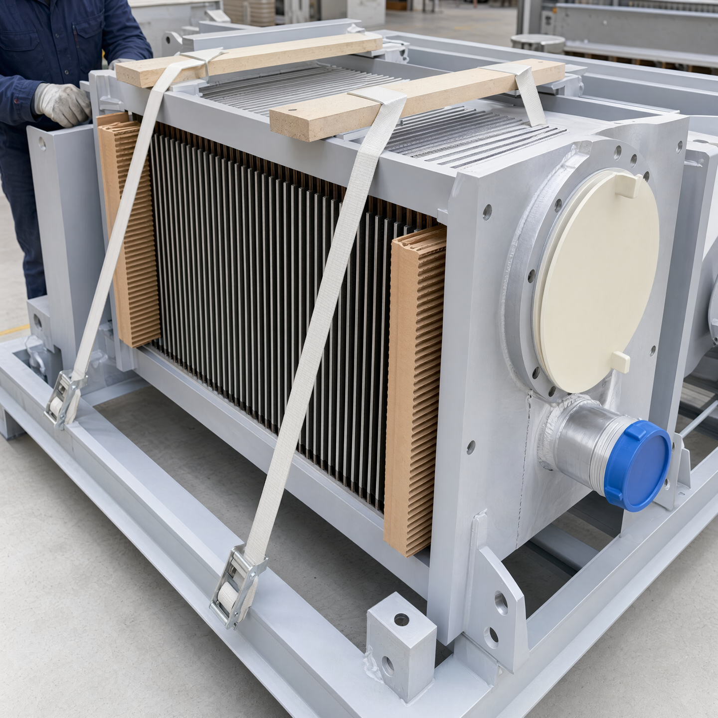
Separate support, restraint and protection
A support carries weight, a restraint controls movement and protection shields a vulnerable surface. One item should not be assumed to perform all three roles. Define where each acts, how it is removed and what interface must remain available afterward.
Write the handling plan around state changes
A bundle does not have one permanent handling method. Its mass path, rigidity, vulnerable surfaces and available support points change as loose tubes become an ordered group, connections are added, the frame takes load and the complete equipment is prepared for handoff.
1. Name the component state before every move
State whether the item is a single finned tube, loose group, ordered bank, connected module, bundle in temporary carriers or complete framed assembly. The same pick point cannot be assumed to suit every state. Identify what is rigid, what can shift and which bare ends, fins, faces or openings are exposed before selecting supports or restraints.
2. Survey the complete movement route
Review the path from current support to destination, including turns, elevation changes, available equipment, frame openings and the space required to remove temporary aids. A lift that works in open floor space may fail at the insertion point because a brace, header or installation feature blocks the approach. Resolve the route before the bundle is ready to move.
3. Define a rigid load path
Carry weight through approved bare-end zones, carrier rails, saddles or robust frame members suited to the actual state. Make the load path visible so slings and supports cannot migrate onto exposed fins. If a spreader, bridge or temporary carrier is needed, define where it connects, how it prevents rolling and when it transfers load to the next support system.
4. Treat protection as a separate layer
Fin guards, edge protectors, flange covers and opening caps shield different vulnerabilities. They should not become unintended structural supports. Keep straps and battens clear of fin tips, avoid loading sealing faces and show how covers remain removable for later fit-up or checks. Protection selected for an intermediate move may differ from the order-specific delivery package.
5. Preserve ordering and orientation
Tube order, connection direction, customer datums and insertion orientation can be lost during regrouping. Use non-damaging identification and external references that remain readable after temporary supports are installed. The handling plan should state which marks control the next operation and which records or drawings explain them, without relying on unreadable or informal shop memory.
6. Plan the transfer into structure and handoff
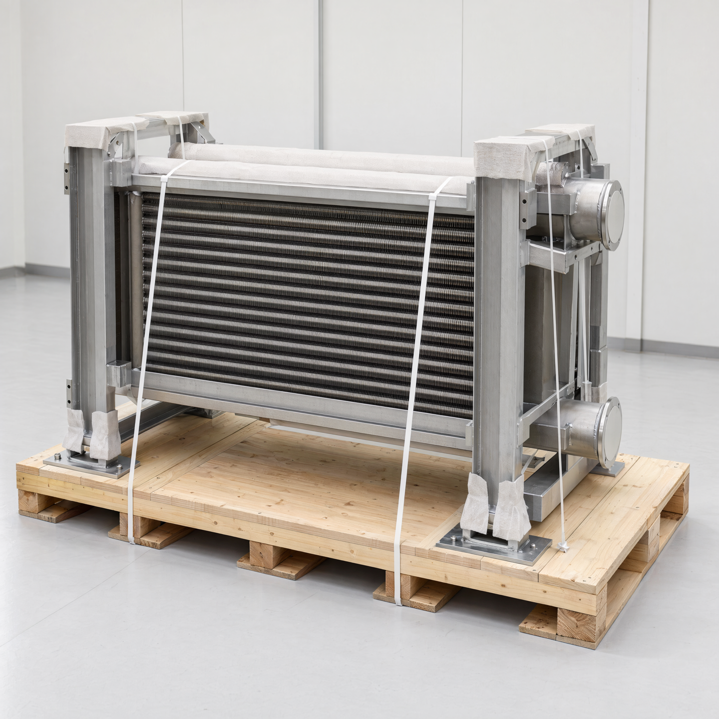
Identify when the frame begins carrying the bundle, how temporary carriers are removed and which side must remain open until connection work is complete. For final handoff, connect restraints to robust frame points and protect the agreed interfaces. The quotation defines whether the unit is complete, split, loose or prepared for later work and which selected records accompany it.
These handling views are illustrative. They do not define a certified lifting device, rated fixture, standard packing system, transport route or guaranteed damage-prevention result. The actual method must follow the project-specific assembly state and agreed manufacturing plan.
Reopen the handling review when the state changes
A revised bundle length, connection body, frame opening, supplied lifting point, installation route or delivery split can invalidate the earlier plan even when the tube count is unchanged. Recheck the mass path, centre relationship, available equipment and vulnerable surfaces against the new state. Do not carry a temporary support or sling arrangement forward simply because it worked before another component was added.
Update the movement sketch, carrier detail, protection note and ordering references together. Tell the next team which temporary aids remain installed, what now carries the weight, which side must stay open and what is removed before connection work. For delivery, confirm that restraints reach robust frame points and that all agreed faces, openings and fins remain protected without being used as structural contact surfaces.
The handling plan should travel with the assembly state rather than exist as a separate generic note. Identify the drawing revision, supported condition, pick or carrier interfaces, exclusion zones and the point where weight transfers into the permanent frame. Mark which protection remains for connection work and which must be removed before a check. If the unit is split for delivery, prepare a separate handoff state for each part. This lets the receiving team verify support, protection and open interfaces without inferring a rated device or a universal transport method from an illustration.