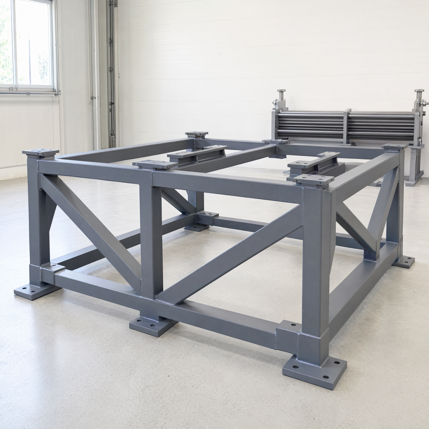
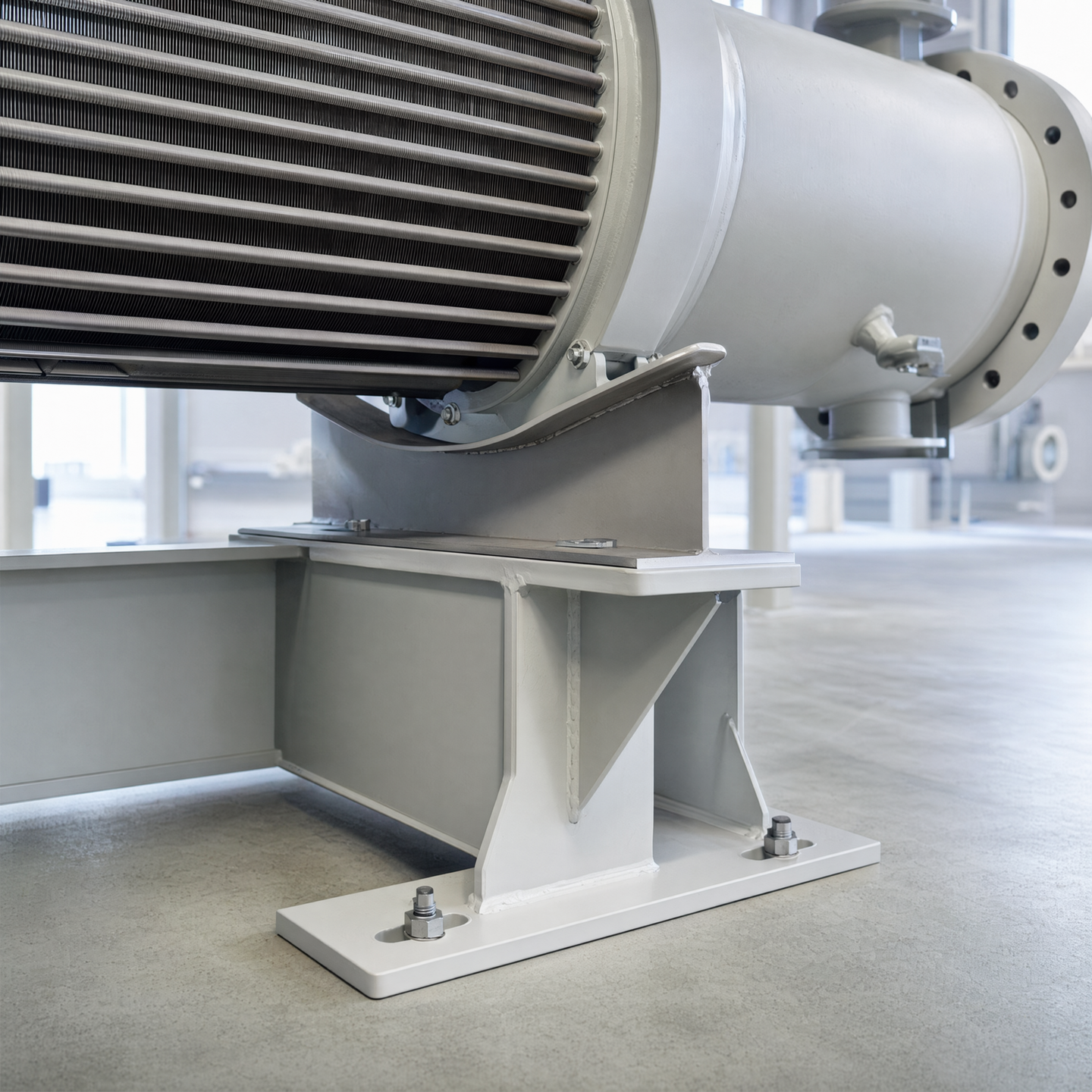
Final alignment is not created by a last inspection. It is carried through a chain of customer-defined interfaces, manufacturing datums, temporary restraints, welded frame states and staged decisions. If the chain is undefined, a frame can look acceptable while empty and still place a flange, mounting foot or tube-bank interface incorrectly after integration. If it is defined, each check can answer a specific manufacturing question while correction remains possible.
This guide addresses fabrication alignment only. It does not calculate support loads, select structural members, verify service stiffness, assess vibration, qualify welds, or approve thermal expansion. The customer remains responsible for thermal duty, heat-transfer design, overall geometry, operating and installation requirements, applied loads, support intent and interface locations. StelTherm may review how the supplied frame and support concept can be detailed, sequenced, assembled and checked within the agreed manufacturing scope.
Define the alignment boundary before reviewing the frame
Start with the interfaces that matter at handoff: mounting planes or feet, connection faces, tube-bank location, support nodes, clearances, lifting or installation interfaces, and any customer-defined centerlines. Identify which requirements apply to loose frame fabrication, which apply after the exchanger is installed, and which apply only in the final delivery state. A tolerance without a named state can be interpreted against incompatible conditions.
The review package should include the controlled overall arrangement, frame and support details, connection layout, installation constraints, customer-defined datums, load information supplied for the design, and the intended assembly sequence. Mark features whose positions are fixed by the customer's design separately from fabrication details that may be proposed for agreement. Where analysis or code verification is required, identify the responsible design authority; a DFM review does not substitute for it.
Convert those inputs into an alignment register. For every critical interface, record the drawing requirement, its reference datum, the stage at which it becomes physically measurable, what later operation may move or obscure it, and who accepts the result. Include unresolved conflicts. The register becomes the bridge between design intent and the inspection route without claiming that every listed measurement or document is automatically part of StelTherm's standard scope.
Read frame stiffness as an assembly-state condition
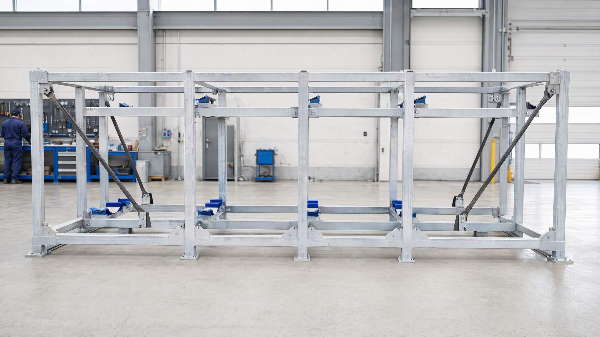
A frame does not have one manufacturing condition. Its effective restraint changes while rails, cross-members, gussets, saddles, base plates, temporary braces and the exchanger body are introduced. An open frame may be easy to adjust but less resistant to movement during local joining. A more closed state may hold one relationship better while locking in another error or blocking access. The manufacturing review maps those state changes; it does not redesign the customer's load path.
Stiffener geometry and joining order can influence welding distortion in the structures actually studied. Shadkam, Ranjbarnodeh and Iranmanesh examined the effect of sequence and stiffener shape on welding distortion of a stiffened panel [2]. Ozcatalbas and Vural investigated welding sequence and distortion forces in steel lattice beams [3]. These papers concern panels and lattice beams, not exchanger frames. They justify asking how member arrangement and sequence interact; they do not provide a frame detail, correction allowance or universal sequence for this product.
At each assembly state, identify what establishes position and what only supports weight temporarily. Show whether the bundle is free, supported, partially connected or fully integrated. Show where a fixture reacts its load and whether that reaction can move a thin member or an interface. Define when temporary bracing is installed and removed. If the design depends on service loads or thermal growth, those conditions must come from the customer or responsible designer and remain separate from shop-state alignment checks.
A useful state map often includes the empty frame, frame under fixture restraint, bundle insertion, connection fit-up, progressive joining, restraint release, final assembly and protected delivery state. It should explain which faces and centerlines are expected to remain common throughout. The map also identifies the moment when a correction changes from a simple fixture adjustment into rework requiring customer approval.
Treat bundle insertion as an alignment state change
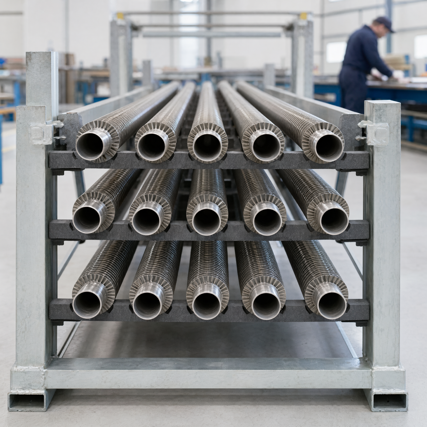
Bundle insertion joins two dimensional histories. The frame has been fabricated and checked in one support condition; the tube group has been prepared and handled through another route. Before they meet, identify the locating features on each, the intended insertion direction, temporary support points, clearances supplied by the design, and the interfaces that must remain free for later connection work. Do not use fins or an unqualified tube edge as an improvised locating surface.
Record the frame state immediately before insertion and the combined state after initial support is established. If the assembly settles, shifts or requires force to reach its locating features, stop and determine whether the cause is a frame condition, tube-group condition, fixture setup or an unresolved design interference. Forcing the components together can hide the original mismatch and transfer it to connection faces or mounting points. Any proposal that changes customer geometry, support intent or interface location returns to the design authority.
The insertion checkpoint should also preserve an exit route. Until the critical relationships are confirmed, avoid a closure operation that prevents removal or adjustment. Define which supports are temporary, when permanent restraint takes over, and what measurement authorizes the next joining state. This makes integration a controlled decision rather than an irreversible handling step.
Choose a datum chain that remains available
Manufacturing datums must be physically repeatable and connected to the customer-defined interface scheme. A convenient raw edge is not automatically a valid reference. A frame rail can guide intermediate work but may not represent the final mounting plane. A flange face can define an important interface yet be too vulnerable or inaccessible to serve every earlier operation. Select stage references deliberately and document how each transfers back to the controlling datums.
For example, an early fixture may establish a base plane and longitudinal centerline while the frame is open. After cross-members are joined, those references can be rechecked before the tube group enters. Connection faces can then be located from the same datum system rather than from whichever member is nearest. The final inspection should demonstrate the agreed relationship between mounting and process interfaces, not a collection of unrelated local dimensions.
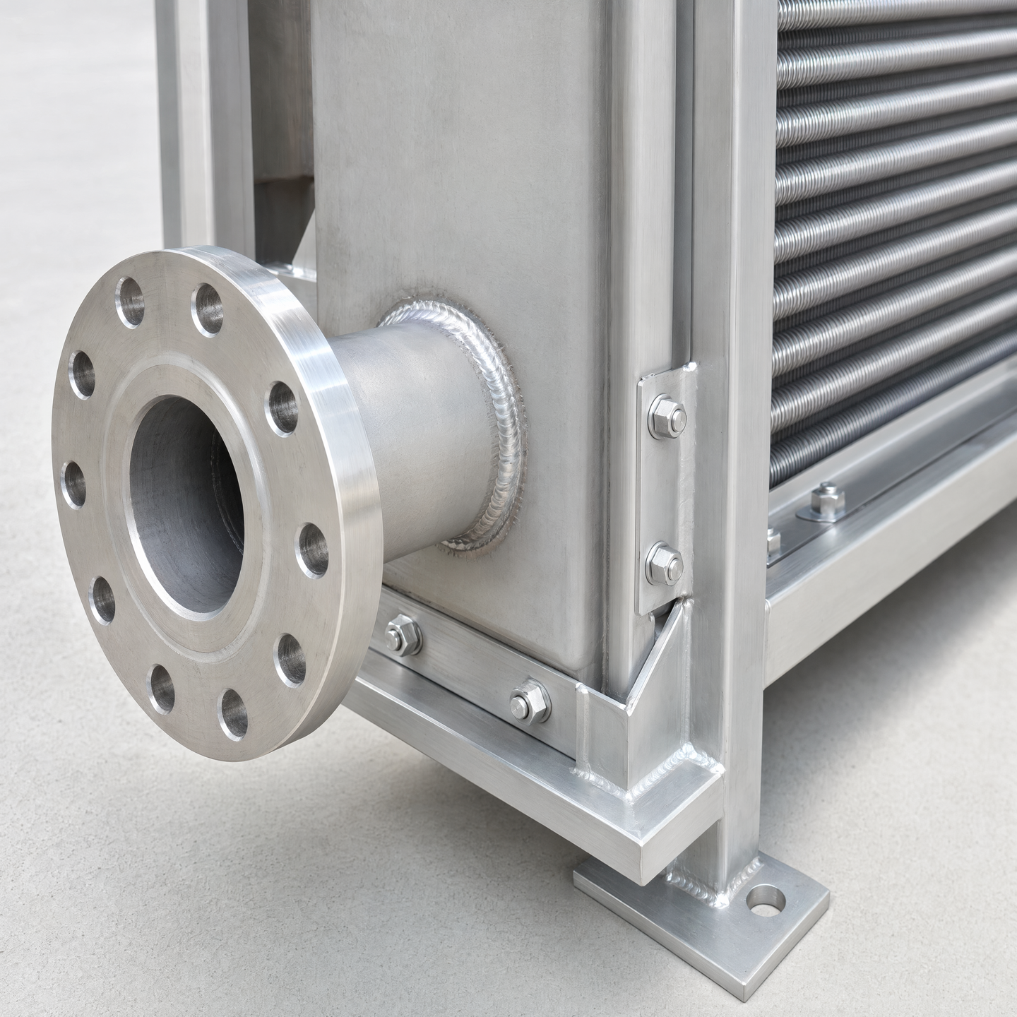
Datum transfer needs a record. Name the reference features, fixture contacts, target points or measurement setup used at each stage. Explain how dirt, weld spatter, protective covers, temporary attachments or later machining could alter the contact. If the datum becomes inaccessible, schedule the required measurement before closure or provide a controlled transfer method. Do not improvise a new reference after a result falls near a limit.
ISO 1101:2017 formally addresses geometrical tolerancing for form, orientation, location and run-out [7]. The official record is cited here only to identify its normative subject. The applicable drawing standard, tolerance symbols, datum system, verification method and edition must be defined in the customer documentation. This page does not reproduce protected requirements or claim conformity.
Plan weld sequence together with restraint release
Welding introduces local heating and cooling into a structure whose restraint changes as fabrication progresses. The result is not determined by weld order alone. Geometry, heat input under the qualified procedure, joint layout, member shape, tack and fixture condition, prior welds and release state all contribute. The manufacturing plan should therefore connect each sequence step to an alignment risk and a measurement checkpoint rather than listing weld numbers without purpose.
Gannon and colleagues reported sequence-dependent residual stress and distortion in their flat-bar stiffened-plate study [1]. Afonso, Rodríguez Martín and Ribeiro found a substantial sequence effect on angular distortion for the specific S235JR butt-joint GMAW experiment they tested [5]. Neither result supplies a percentage or best sequence for an exchanger. They demonstrate that the sequence variable can alter the measured result in bounded configurations.
External restraint must be recorded with the sequence. Sun and Dilger studied the combined influence of sequence and external restraint on buckling distortion in thin-plate arc-welded joints [4]. For a frame review, the relevant lesson is not to maximize restraint blindly. It is to state what is restrained, where the reactions enter the assembly, when the restraint is released, and which interfaces are remeasured afterward. A dimension held only under fixture load is not necessarily the delivered dimension.
Sequence alternatives can then be compared against project-specific objectives: preserve a mounting plane, keep a connection accessible, avoid trapping the bundle, maintain a usable datum, and leave an agreed correction path. A proposed alternating or balanced route should be treated as a hypothesis to validate on the actual geometry, not a slogan. If a change affects a customer-controlled location or structural design feature, return it for approval before fabrication detail is released.
Separate fit-up control from final acceptance
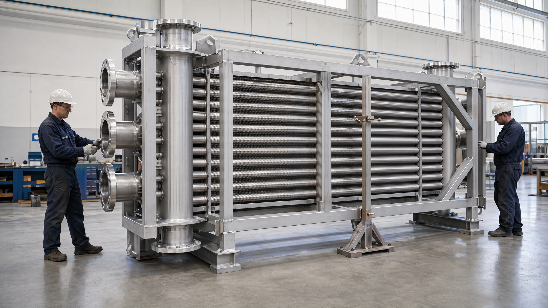
Fit-up dimensions guide the next operation; final acceptance confirms the delivered state against the agreed requirement. They may use related features but they are not interchangeable. An intentional fit-up offset or temporary restraint position must be labeled as a process control, not as a relaxed product requirement. The drawing requirement remains unchanged unless the customer or design authority approves a revision.
Define the response to an out-of-sequence result. If an empty frame is outside its process target, can it be adjusted before insertion? If a flange moves after a nearby weld, is correction allowed before another connection closes access? If the mounting plane changes after restraint release, who evaluates the result? The route should stop at the earliest useful point rather than carrying a known misalignment into a more expensive state.
Protect measurement surfaces throughout the sequence. Temporary welds, spatter, coatings, handling damage or local grinding can change a reference. Mark no-contact and no-attachment zones on the fabrication detail where needed. When protection is installed before delivery, make sure the final agreed check occurs first or remains possible without disturbing the interface.
Measure in stages while each result can guide action
A stage plan should specify the characteristic, reference, instrument or method category as agreed, measurement state, responsible party, record and decision. Typical decision stages are frame fixture setup, open-frame completion, pre-insertion verification, connection fit-up, progressive post-weld checks, restraint release and final delivery state. The exact checks are project-specific; this list does not promise a standard report or a particular StelTherm inspection capability.
Boldsaikhan and colleagues used robotic metrology and a least-squares flatness estimate to compare sheet condition before and after refill friction stir spot-welding sequences [6]. Their aluminum lap-panel method and numerical result do not transfer to exchanger frames. The study does support a disciplined pattern: define a measurement method, capture a baseline, repeat it after a controlled sequence, and compare like with like rather than relying on visual memory.

Measurement timing and environmental conditions should be consistent with the contractual need. Do not add an unsupported universal waiting time or a fictitious tolerance. If temperature, support condition or elapsed time matters to the customer's acceptance basis, it must be stated. Record whether the assembly is free, fixtured, supported at installation points or sitting in another temporary condition.
Use an alignment review table that drives decisions
| Stage | Question to resolve | Evidence to retain |
|---|---|---|
| Design input | Which customer interfaces, datums, loads and installation constraints control? | Controlled drawing revision and responsibility owner |
| Frame detail | Which members, feet or target features carry the stage reference? | Annotated datum and state map |
| Fixture plan | What holds position, where does restraint react, and when is it released? | Fixture envelope and release checkpoint |
| Open-frame check | Which relationships must be accepted before bundle insertion? | Stage results tied to the frame identifier |
| Fit-up | Which interfaces are checked before joining closes access? | Fit-up record and unresolved issue disposition |
| Join sequence | How are order, restraint, access and expected movement coordinated? | Approved sequence revision and hold points |
| Released assembly | What changed after fixture or temporary support removal? | Remeasurement from the same defined references |
| Final state | Which agreed interfaces are checked before protection and handoff? | Order-specific acceptance and document package |
Define correction authority before a limit is challenged
An alignment plan is incomplete without a disposition route. State who may adjust a fixture, change a tack sequence, add a temporary support, propose local correction or request a drawing revision. Separate reversible process tuning from changes to customer geometry. Document the reason, affected interfaces and verification needed after the action. This is particularly important when a local correction can propagate into another connection or mounting point.
Avoid “make it fit” instructions. They conceal design authority and erase the baseline needed to learn from the result. If a part is accepted by concession, identify the exact characteristic and approving authority; do not silently update the next unit from an unrecorded deviation. If rework could affect material condition, weld integrity or a customer requirement, route it through the appropriate controlled review rather than treating dimensional correction as harmless.
The final StelTherm DFM output should be a set of frame and support detailing questions, an agreed datum and state map, proposed sequence checkpoints, and a measurable finished support arrangement based on customer-approved inputs. It does not certify structural adequacy or thermal performance. The actual fabrication, welding, examination and documentation scope remains whatever the quotation and approved package define.
References
- L. Gannon, Y. Liu, N. Pegg and M. Smith, “Effect of welding sequence on residual stress and distortion in flat-bar stiffened plates,” Marine Structures, 2010. https://doi.org/10.1016/j.marstruc.2010.05.002
- S. Shadkam, E. Ranjbarnodeh and M. Iranmanesh, “Effect of sequence and stiffener shape on welding distortion of stiffened panel,” Journal of Constructional Steel Research, 2018. https://doi.org/10.1016/j.jcsr.2018.07.010
- Y. Ozcatalbas and H. I. Vural, “Determination of optimum welding sequence and distortion forces in steel lattice beams,” Journal of Materials Processing Technology, 2009. https://doi.org/10.1016/j.jmatprotec.2008.02.051
- J. Sun and K. Dilger, “Influence of welding sequence and external restraint on buckling distortion in thin-plate arc-welded joints,” Journal of Advanced Joining Processes, 2023. https://doi.org/10.1016/j.jajp.2023.100157
- I. S. Afonso, M. Rodríguez Martín and J. E. Ribeiro, “Effect of Welding Sequence in Angular Distortion on Butt Joint GMAW Process,” Applied Sciences, 2022. https://doi.org/10.3390/app122010402
- E. Boldsaikhan, M. Milhon, S. Fukada, M. Fujimoto and K. Kamimuki, “Metrology of Sheet Metal Distortion and Effects of Spot-Welding Sequences on Sheet Metal Distortion,” Journal of Manufacturing and Materials Processing, 2023. https://doi.org/10.3390/jmmp7030109
- ISO, “ISO 1101:2017 — Geometrical product specifications (GPS) — Geometrical tolerancing — Tolerances of form, orientation, location and run-out.” Official ISO record.
Alignment-control atlas
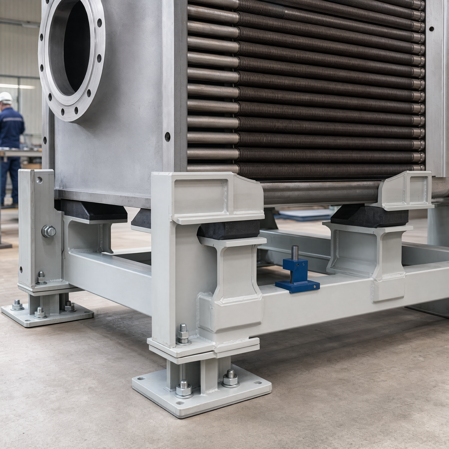
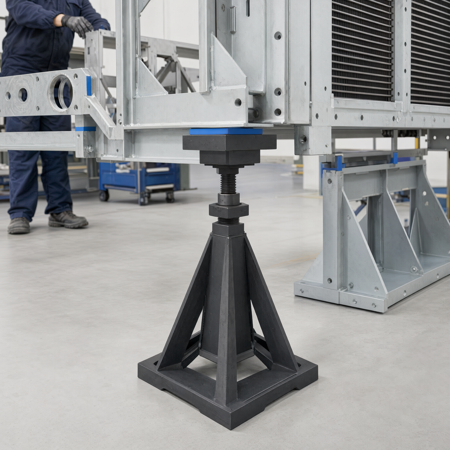
Alignment is carried through a chain of physical references. The useful question is not whether the finished frame looks straight; it is which feature locates the next operation, how that feature is protected from movement and when the route checks it again.



Carry one datum story through every stage
The review should name the reference, the component controlled from it, the expected movement risk and the stage at which the relationship is checked. If a later operation removes the reference, define the transfer before fabrication starts.
Develop a datum-control plan before the frame becomes rigid
A useful datum plan connects customer-defined interfaces to shop references that remain available during fabrication. It does not invent a universal tolerance or structural design basis. It explains how the agreed geometry is established, protected, transferred and checked through the chosen assembly route.
1. Start from functional interfaces
Identify the mounting planes, flange faces, nozzle positions, support locations and installation-envelope features controlled by the customer design. Separate functional interfaces from convenient fabrication edges. A cut edge or temporary rail may help locate work, but it should not replace the interface that governs the delivered equipment unless that transfer is explicitly defined and approved.
2. Select working references that remain accessible
Choose frame rails, pads, fixture surfaces or external tabs that can be reached at the stage they are needed. State how each working reference relates to the customer datum. If a component, weld or protective cover will hide the reference, plan the next reference before that happens. A datum that exists only in the model cannot control physical assembly without a readable shop relationship.
3. Coordinate fixtures and temporary restraint
Define what establishes position, what prevents movement and what carries weight. These functions may require different features. Temporary supports should not compete with bundle insertion, joining access or measurement paths. The plan should also state when restraint is released; removing it before the affected relationship is checked can discard the only practical opportunity to identify movement.
4. Relate joining sequence to movement risk
Every joining stage changes stiffness and may change direction or magnitude of movement. Review the sequence across the assembly rather than treating each joint independently. Keep customer-controlled interfaces referenced while structure is added, and identify the point where balanced work, staged restraint or an intermediate check is needed. Exact procedures remain order-specific and are not implied by the illustration.
5. Transfer control when the assembly state changes
Bundle insertion, header fit-up or installation of a major brace may make the original frame reference unusable. Before the transition, establish the external feature that carries control into the next state and record its relationship. A deliberate transfer prevents different teams from measuring the same interface from unrelated origins and drawing conflicting conclusions.
6. Check while action is still possible
Place checks after the operation most likely to affect the relationship and before the next operation closes access. Typical stages may include open frame, supported bundle, fitted connection, post-join interface and pre-protection handoff. The customer requirement defines acceptance; the manufacturing plan defines when the agreed requirement can be evaluated and, if needed, corrected.
Frame and support imagery is illustrative and does not establish load capacity, structural calculation, material grade, tolerance or inspection result. Customer-supplied loads and interfaces remain controlling inputs to the project-specific review.
Reopen the datum plan after any structural or sequence revision
A changed brace, support node, bundle insertion direction, connection orientation or joining sequence can remove a reference or alter the stage where movement occurs. Trace the revised operation from the customer interface back through the working datums. Confirm that fixtures still fit, temporary restraint does not block access and the next check occurs before the affected relationship becomes hidden or rigid.
Revise the frame detail, fixture concept, sequence note and staged-check plan as one set. If control transfers to a new external tab or rail, document how that reference relates to the customer datum before the original is lost. The final check then confirms the agreed interface against the current route rather than comparing it with a reference that belonged to an earlier assembly state.
A datum plan also needs a clear handoff between stages. State which feature establishes position, which temporary reference copies that relationship, when the original becomes unavailable and what evidence confirms the transfer. A fixture label alone is not enough if another team cannot trace it back to the customer interface. When the frame, bundle or connection becomes rigid, record the check that closed the preceding stage and the reference that controls the next one. This prevents a local alignment convenience from silently replacing the approved installation or connection basis.