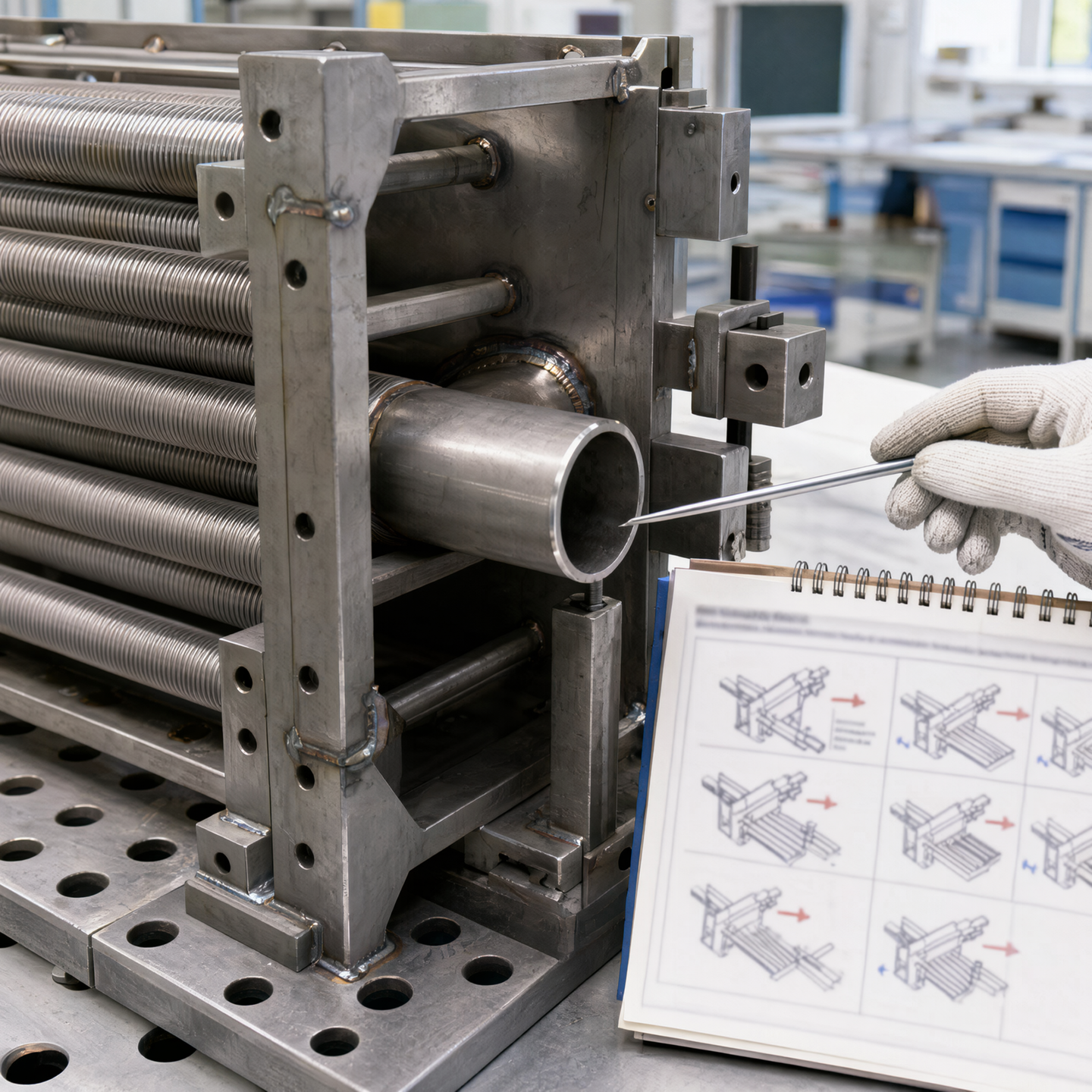
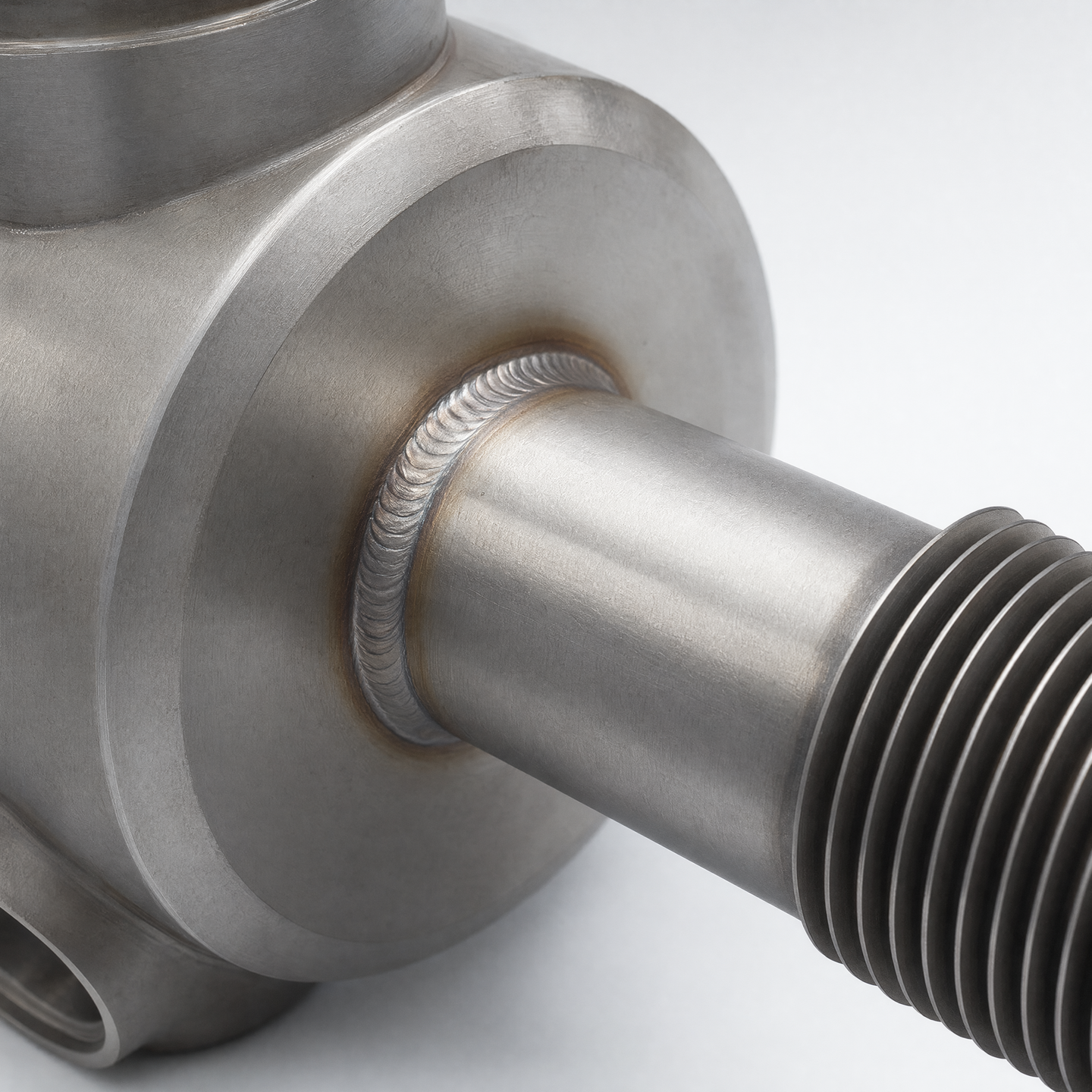
A weld symbol can define a joint without proving that the joint is reachable in the state in which it will be made. In a finned-tube exchanger, the approach path may compete with fins, tube rows, headers, flange faces, support members, temporary fixtures and the next component in the sequence. A useful manufacturability review therefore treats access as a three-dimensional, time-dependent property of the assembly rather than as empty space around an isolated line.
This guide explains the information needed to review that problem. It does not select a welding process, qualify a procedure, design the exchanger, or establish an acceptance level. No equipment range, welder qualification, test capability or completed StelTherm project is asserted here. The images are illustrative references for access, sequence and checking; the customer drawing and the agreed fabrication package remain controlling.
Keep the design and manufacturing responsibilities distinct
The customer owns thermal duty, heat-transfer design, overall geometry, material and interface requirements, governing project requirements, and approval of changes to those inputs. StelTherm's role is narrower: review the supplied design for fabrication access, propose practical detailing or sequence changes, identify what each change affects, and build only the scope agreed through quotation and drawing review. A manufacturing proposal cannot silently move a nozzle, reduce a tube bank, change a material, or alter a customer-controlled envelope.
Begin the access review with a controlled overall arrangement and joint schedule. For every connection, identify the parts being joined, the customer-required location and orientation, the current weld representation, surfaces that must remain protected, nearby finished interfaces, and the assembly state in which joining is expected. Mark provisional features separately from approved ones. If the process, examination method or acceptance document is already customer-mandated, include it; if not, record it as an open project decision rather than assuming a default.
The output of this first pass is not a promise that every joint is feasible. It is an access issue register. Each entry should point to a drawing view or model location, describe the obstruction or missing information, state the assembly stage affected, and name the person or organization with authority to approve a change. That register keeps a local shop concern from becoming an undocumented design revision.
Map four access envelopes, not only the joint
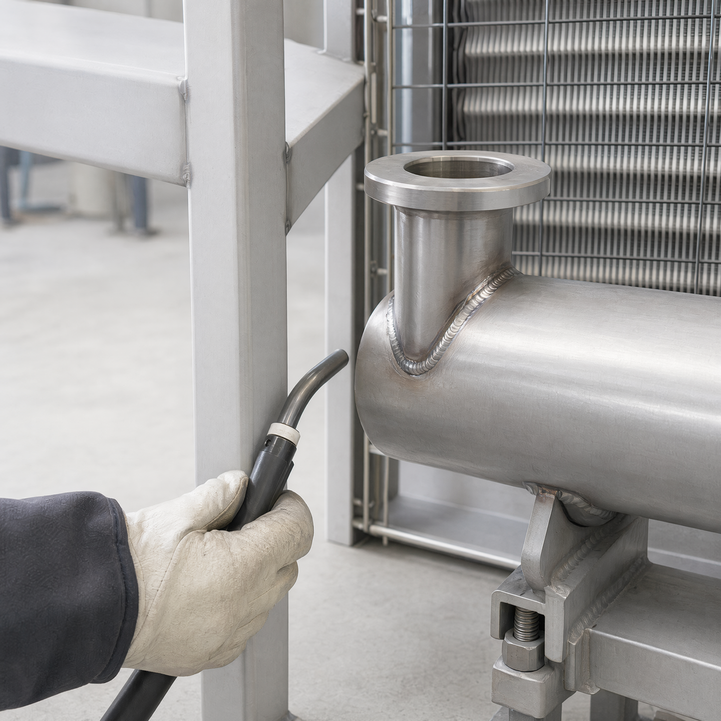
The first envelope belongs to the joint itself. It includes the prepared edges or surfaces, the local orientation, the route by which the parts meet, and the space required to hold fit-up. The second belongs to execution: torch or tool approach, working angle, line of sight, hand or automated-head movement, cable and hose routing, and clearance for consumables. The exact envelope depends on the agreed process and must be reviewed by the responsible welding team; this article does not prescribe it.
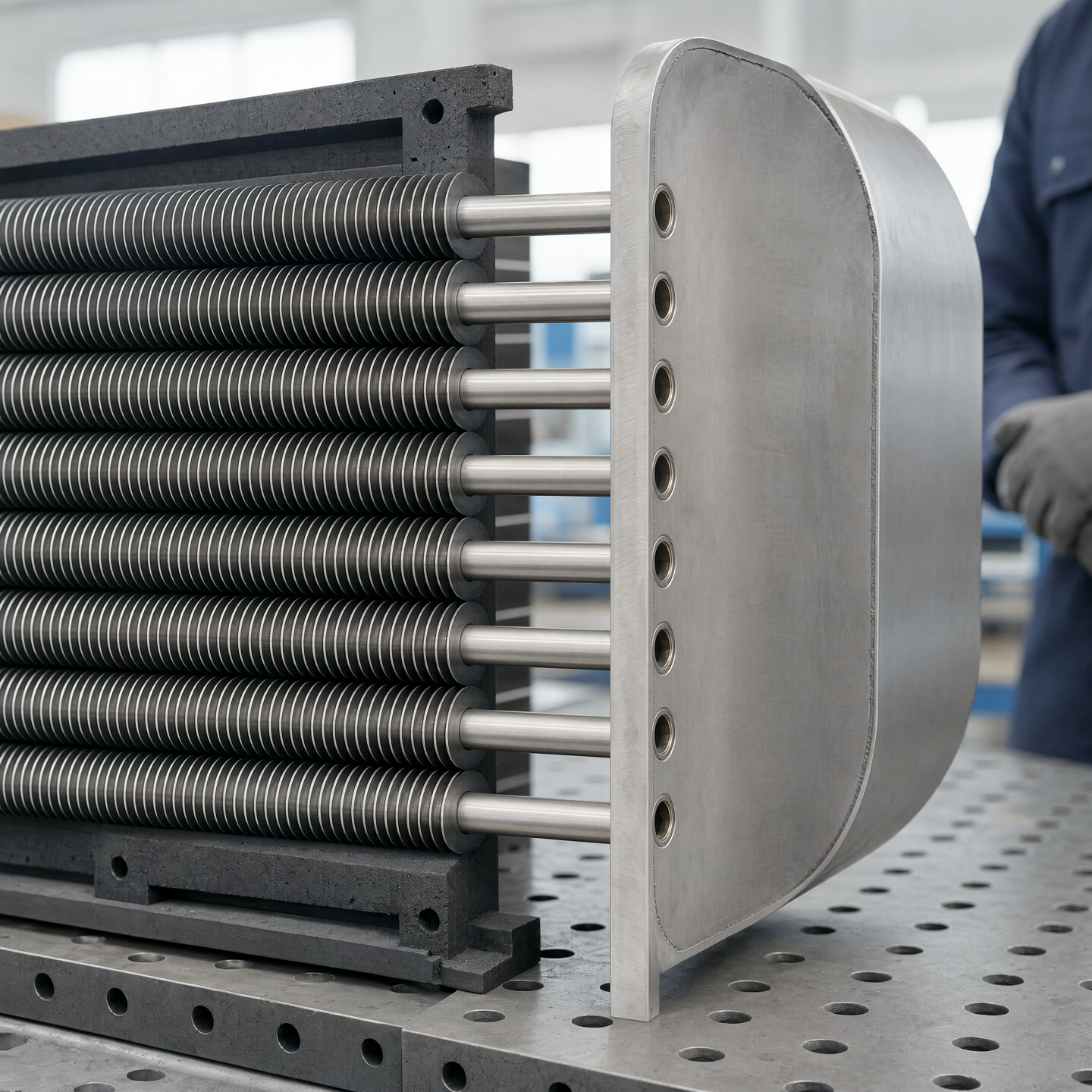
The third envelope belongs to support and restraint. A clamp may solve fit-up but occupy the same space needed for joining. A temporary strongback may preserve position while hiding an adjacent seam. The fourth belongs to verification and correction: cleaning, direct visual access where required, measurement, surface preparation, repair access and a route to remove temporary aids without damaging fins or finished faces. Passing only the execution envelope can still leave an uninspectable or uncorrectable joint.
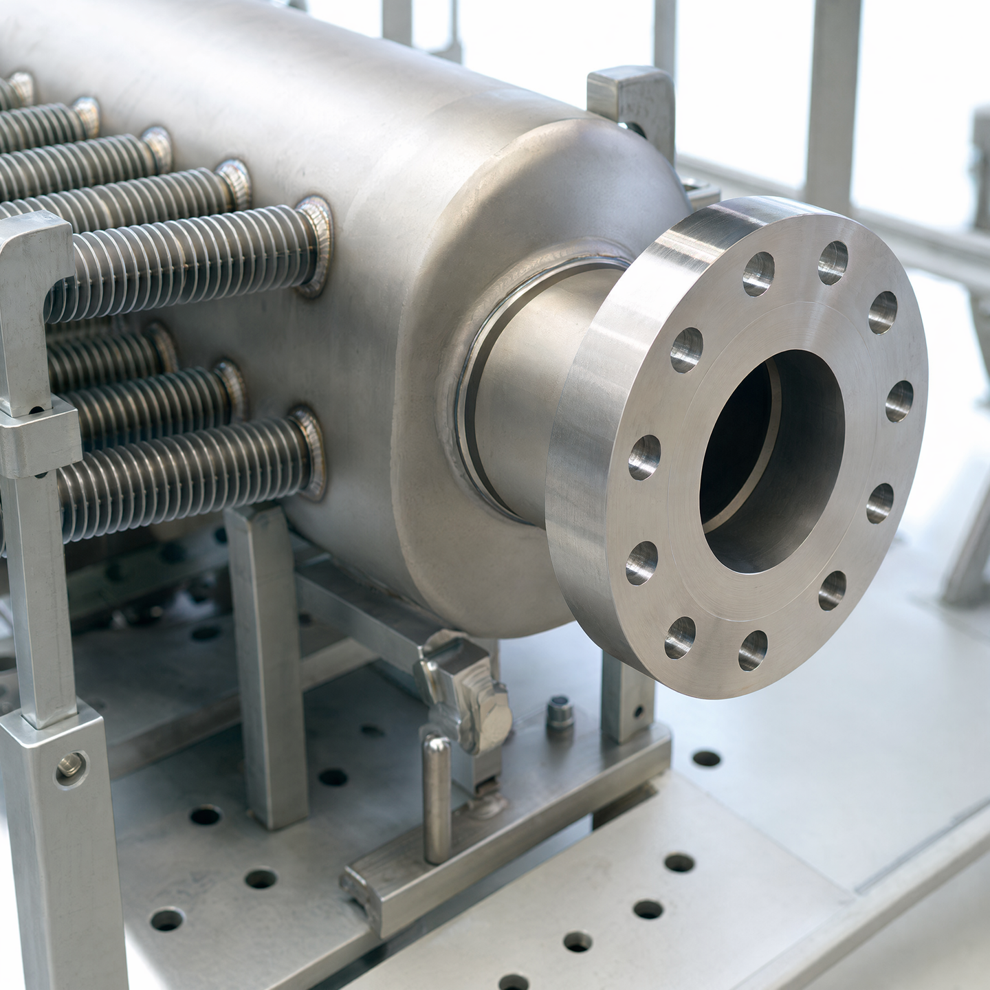
Make the envelopes visible with section views, transparent model states or annotated screenshots. A single general-arrangement view rarely shows the approach path behind a tube row or beneath a header. Add the fixture in the review state even if it is not a delivered component. Show removable covers, temporary braces and protective barriers. Where a tool or examination path is not yet selected, reserve a review zone and flag the decision rather than drawing a misleadingly precise clearance.
| Envelope | Information to show | Question to close |
|---|---|---|
| Joint | Parts, orientation, edge or surface condition, local geometry | Can the parts be positioned and held as drawn? |
| Execution | Proposed approach direction, surrounding obstructions, service routing | Can the agreed operation be performed without a hidden conflict? |
| Restraint | Fixture, clamps, temporary supports, release direction | Does position control consume the required work space? |
| Verification | Viewing, measurement, cleaning and correction paths | Can the agreed check occur before access closes? |
Access belongs to the assembly state in which the joint will actually be made, checked and released.
Model assembly states before choosing the closing joint
Access changes whenever a tube group, header, frame member, flange, brace or fixture is added. Review the product as a sequence of states: loose components, subassembly fit-up, partially closed frame, integrated exchanger and final delivery condition. For each state, list the joints available, datums visible, temporary supports active, vulnerable surfaces exposed and checks still possible. The sequence should have an explicit reason; convenience at one joint is not enough if it creates an inaccessible joint later.
Peer-reviewed studies on other welded structures show why sequence deserves project-specific analysis. Gannon and colleagues compared welding sequences in flat-bar stiffened plates and reported sequence-dependent residual stress and distortion in the studied configuration [1]. Afonso, Rodríguez Martín and Ribeiro likewise found that sequence substantially influenced angular distortion in their S235JR butt-joint GMAW experiment [2]. These studies do not supply an exchanger sequence or a transferable correction value. They support the narrower conclusion that order can change the final geometric result and should not be left implicit.
A practical state review often reveals three classes of joint. An early joint must be completed before insertion or enclosure. A hold-open joint is delayed to preserve access for another operation. A closure joint completes the assembly after upstream checks are accepted. The drawing set or fabrication plan should name those states and define the approval point between them. If a closure joint also controls a customer interface, plan how its position will be checked after joining.
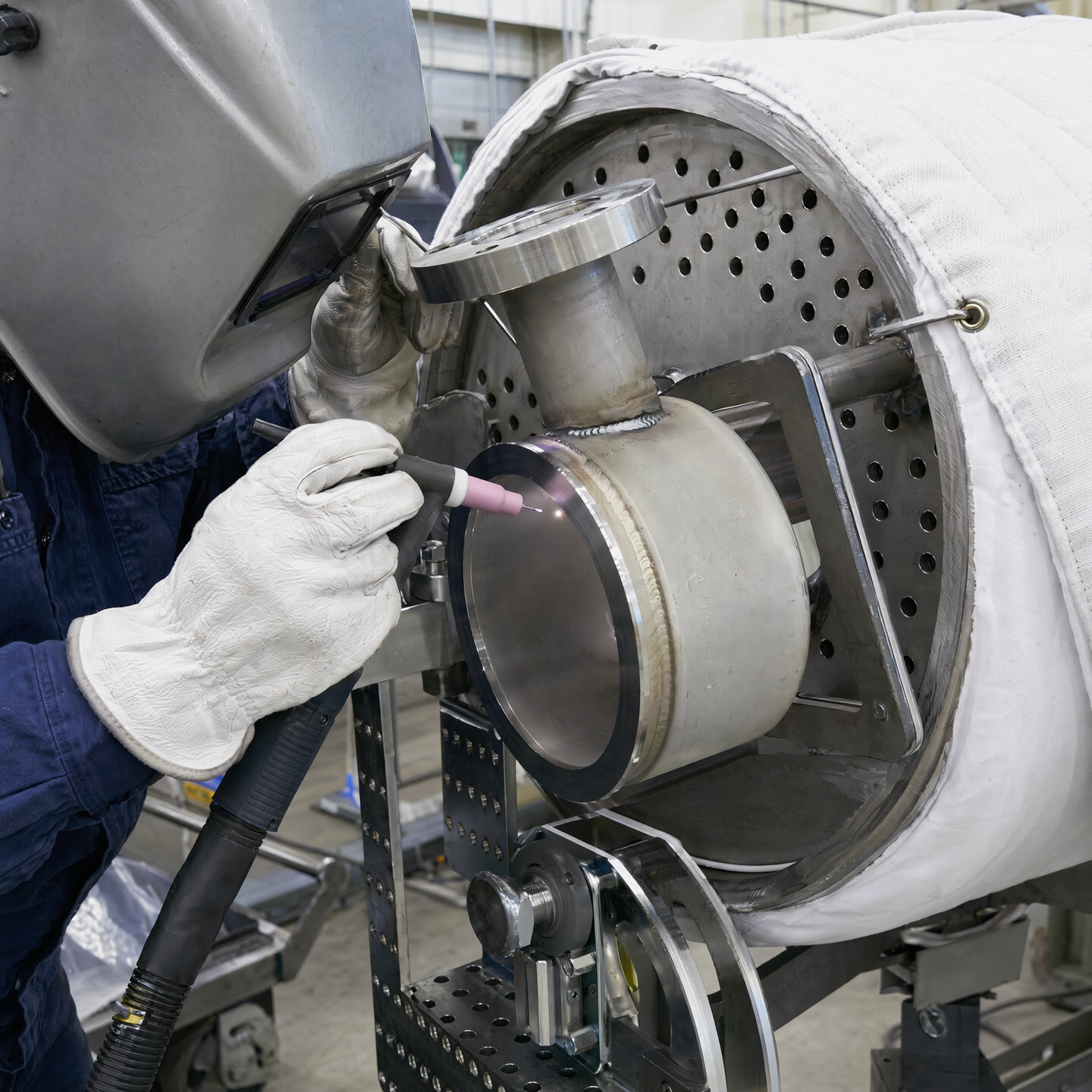
Do not convert the research into a rule that symmetrical or alternating welding is always best. Deng, Murakawa and Liang's large-structure simulation work addresses welding distortion as a coupled thermal and structural problem [3]. The actual result depends on geometry, heat source representation, boundary conditions and sequence. The exchanger review therefore records the proposed route, its assumptions and the features to remeasure; it does not copy a sequence from a plate, beam or simulation model.
Coordinate fixtures, tack stages and permanent joining
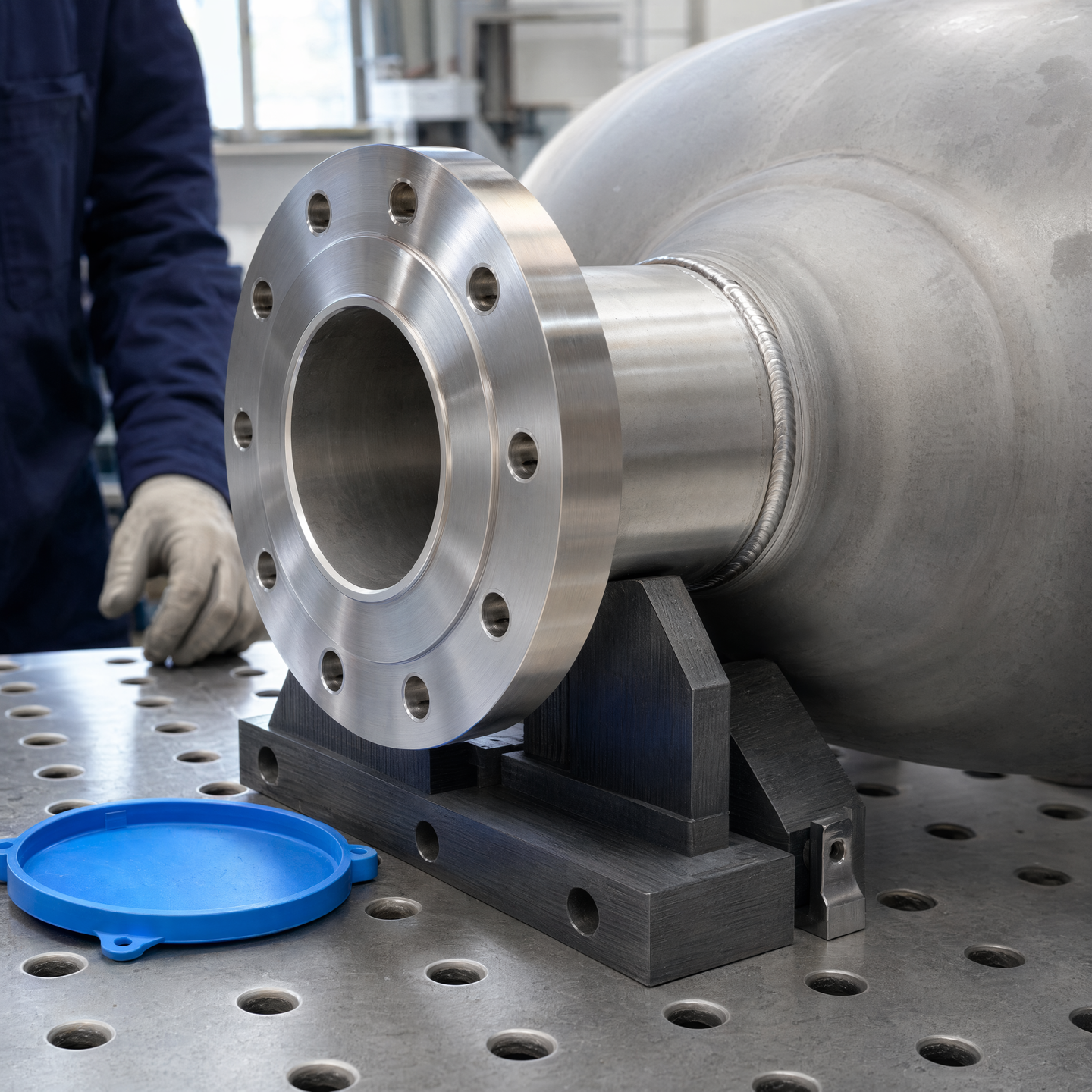
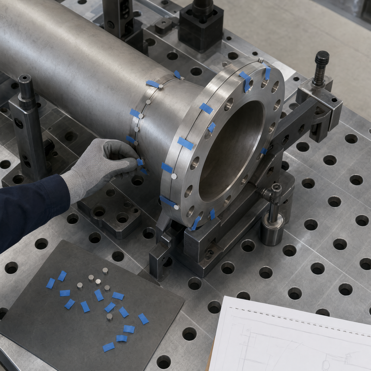
Access and restraint are not independent. The fabrication team may need a fixture to hold a flange face, tube-end group or frame node relative to a datum while joining occurs. The model should show the fixture body, clamp direction, installation and removal paths, and the stage at which its load is released. If the fixture is omitted from the access review, the apparent free space may never exist on the shop floor.
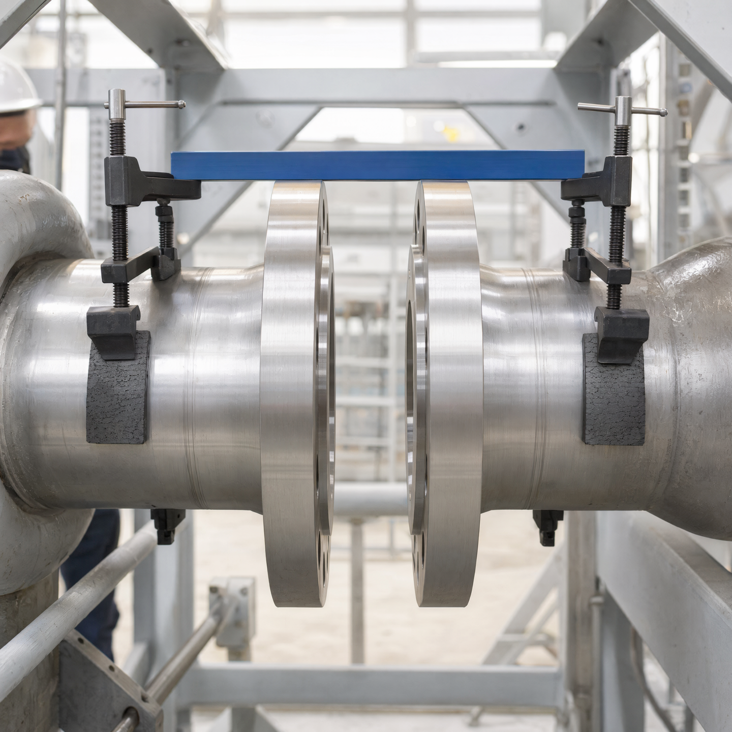
External restraint can change distortion behaviour as well as access. Sun and Dilger studied the combined influence of welding sequence and external restraint on buckling distortion in thin-plate arc-welded joints [4]. That paper concerns its own specimens, not finned-tube exchanger frames. Its relevance here is methodological: the sequence review must include the restraint condition under which the joint is made and the condition after release. “Held to drawing” is incomplete unless the release and remeasurement state are defined.
Tack welds and temporary attachments also occupy sequence positions. The fabrication plan should identify what they locate, which later operation depends on them, when they may be removed, and what surface restoration is required. Avoid placing a temporary attachment where it blocks a required final joint or creates a conflict with a protected finned region. Any temporary-joint details and acceptance requirements remain subject to the agreed welding documentation and customer requirements.
Protect fins, faces and datums while preserving approach paths
Fins are functional geometry supplied or selected for the customer design, and this guide makes no claim about their material or attachment route. During access planning, treat them as vulnerable surfaces whose protection can itself consume space. A heat shield, removable guard or local cover must not force an unsafe or impractical approach, and the joining route must not depend on pressing tools, cables or fixtures against fin edges.
Finished flange faces, tube openings and mounting surfaces need a similar map. Mark no-contact zones and the stage at which temporary protection is installed. Keep the working datum identifiable after protection is applied. If a datum target becomes hidden by a cover or brace, create a controlled transfer feature or schedule the relevant measurement earlier. The customer should approve any change that affects the defined interface; StelTherm can propose the manufacturing detail but does not redefine the interface.
Access also affects cleanliness and foreign-material control. Specify how an opening is protected between operations, when covers are removed, and how the joint area is prepared under the agreed process documentation. Do not rely on an illustrative image as evidence of a cleaning method, protected material grade or finished quality. The image explains spatial relationships only.
Reserve inspection and correction access at the useful stage
An inspection requirement is incomplete if the manufacturing route removes the physical path needed to perform it. The package should identify the characteristic to be checked, the applicable document, the stage, the required surfaces or sight lines, the datum or reference, and the record expected. Where later assembly hides the area, the review must decide whether the check is completed and accepted earlier or whether the design and sequence should preserve later access.
ISO 17637:2016 is formally titled “Non-destructive testing of welds — Visual testing of fusion-welded joints” [6]. That official record is cited only to identify the standard's published scope. It does not establish that the standard governs a particular order, that StelTherm performs the examination, or that any illustrated joint meets it. If the customer invokes that or another inspection document, the applicable edition, acceptance basis, examiner responsibility and reporting requirement must be agreed from the controlled text.

Correction access deserves its own decision. If a measured interface is outside the agreed requirement, can the relevant restraint be adjusted without damaging the tube bank? Is a local repair physically reachable after the next component is installed? Who may approve rework that changes a customer-controlled feature? A final check with no planned response path can detect a problem without providing a controlled way to resolve it.
Put access decisions into the controlled package
ISO 2553:2019 addresses symbolic representation of welded joints on drawings [5]. A symbol communicates defined joint information under the applicable standard; it does not replace an assembly-state access review. Pair the controlled weld representation with views, sequence identifiers and issue records that show how the joint is reached in this particular product.
| Show or state | Manufacturing question | Review output |
|---|---|---|
| Joint identity and adjacent components | What blocks approach, visibility, restraint or service routing? | Annotated access view and affected drawing reference |
| Assembly-state sequence | Which installed component closes access to the next joint? | State list with early, hold-open and closure joints |
| Fixtures and temporary supports | What holds position, and how is it installed, released and removed? | Fixture envelope and release checkpoint |
| Protected surfaces | Which fins, faces, openings and datums cannot be contacted or obscured? | Protection zones and permitted handling path |
| Critical interfaces | Which locations need staged dimensional checks? | Datum, timing and responsible review point |
| Inspection requirement | What physical access and condition does the agreed method require? | Method, stage, acceptance source and record responsibility |
| Change authority | Who approves a geometry or sequence change that affects the design basis? | Open item, owner, due state and controlled disposition |
Use a close-out gate before components commit the route
The review is ready to close when each joint has an identified assembly state, its working and restraint envelopes have been considered, protected surfaces are visible, staged checks are assigned, and open changes have an owner. High-risk or unresolved items should remain hold points. A quotation assumption must not be treated as customer approval, and an email discussion should not silently supersede a controlled drawing.
The useful StelTherm deliverable is a prioritized access issue list, proposed sequence or detailing changes, the customer decisions required, and an agreed fabrication-detail update. The deliverable is not thermal validation and does not guarantee a welding outcome. Project-specific welding procedures, qualifications, inspection methods, acceptance requirements and records are established only in the agreed order documentation.
Send the overall arrangement, joint locations, surrounding geometry, proposed assembly order, customer restrictions and inspection expectations together. That context allows the manufacturing review to identify where access exists, where it closes, and which decision must be made before material or components are committed.
References
- L. Gannon, Y. Liu, N. Pegg and M. Smith, “Effect of welding sequence on residual stress and distortion in flat-bar stiffened plates,” Marine Structures, 2010. https://doi.org/10.1016/j.marstruc.2010.05.002
- I. S. Afonso, M. Rodríguez Martín and J. E. Ribeiro, “Effect of Welding Sequence in Angular Distortion on Butt Joint GMAW Process,” Applied Sciences, 2022. https://doi.org/10.3390/app122010402
- D. Deng, H. Murakawa and W. Liang, “Numerical simulation of welding distortion in large structures,” Computer Methods in Applied Mechanics and Engineering, 2007. https://doi.org/10.1016/j.cma.2007.05.023
- J. Sun and K. Dilger, “Influence of welding sequence and external restraint on buckling distortion in thin-plate arc-welded joints,” Journal of Advanced Joining Processes, 2023. https://doi.org/10.1016/j.jajp.2023.100157
- ISO, “ISO 2553:2019 — Welding and allied processes — Symbolic representation on drawings — Welded joints.” Official ISO record.
- ISO, “ISO 17637:2016 — Non-destructive testing of welds — Visual testing of fusion-welded joints.” Official ISO record.
Access decision atlas
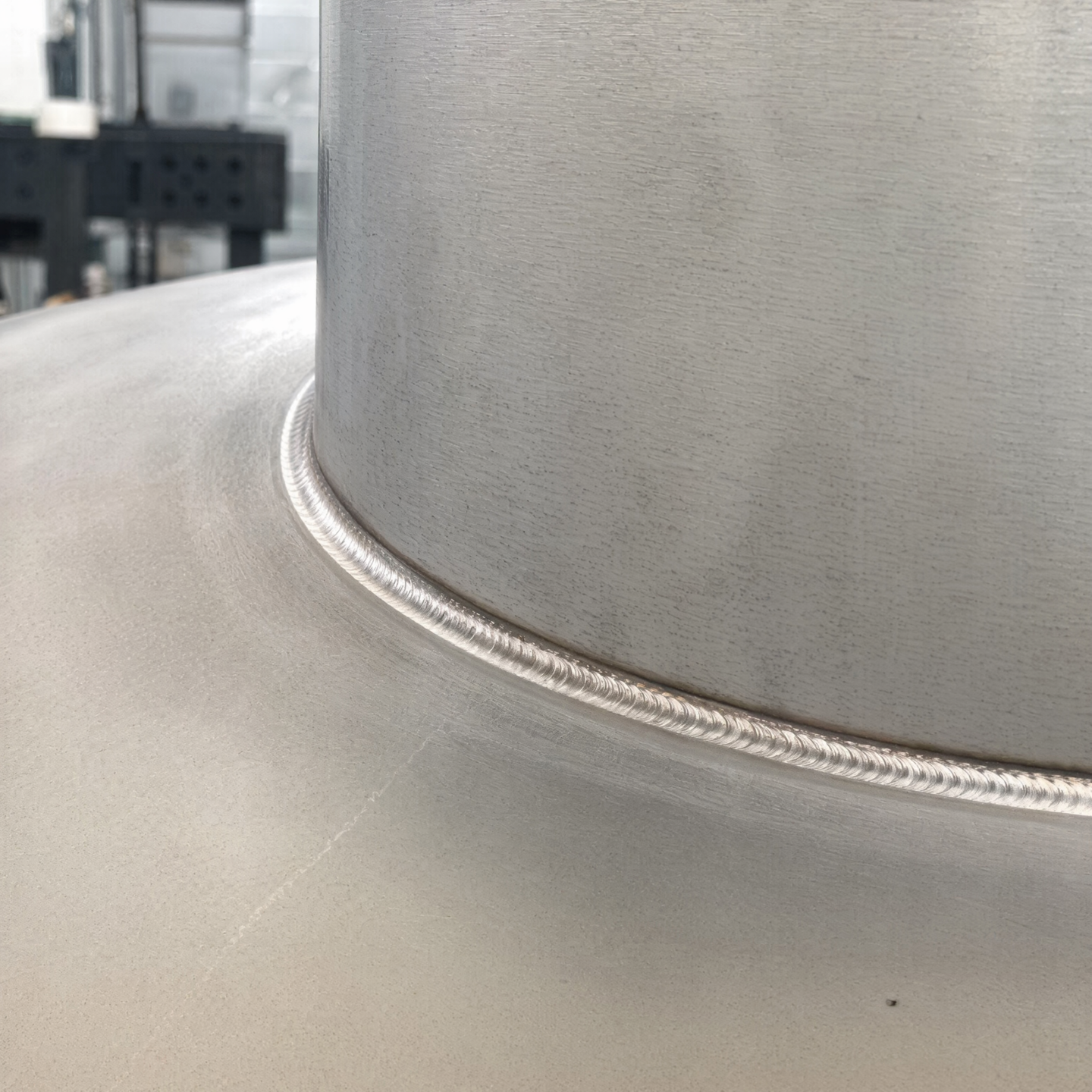
These illustrations show six different states of the same manufacturing question. None establishes a welding process, qualification or acceptance result. Use them to identify the joint, the obstruction, the temporary restraint and the stage at which the connection can still be reached and checked.
Four answers to carry into the fabrication route
- Which assembly state gives the intended joint a workable approach path?
- Which fixture or temporary support holds position without blocking that path?
- Which later component closes access, and what must be completed before it arrives?
- Which interface or datum must be checked while the joint remains visible?
From access review to released fabrication detail
An access review is useful only when its answer survives into the documents and sequence used for fabrication. The following steps turn a visual concern into an agreed manufacturing basis without changing the customer's thermal duty, overall geometry or required interfaces by implication.
1. Name the real assembly state
Define which tubes, headers, flanges, frame members, fixtures and temporary supports are present when the joint is made. A model view that hides components or shows an impossible open condition can make access appear easier than it will be on the floor. Identify the installation direction of the next component and the side that remains available to the operator.
2. Describe the complete approach path
The required envelope includes more than the final tool position. It includes entry, working angle, hand position, visibility, cable or hose route, fixture clearance and a safe exit path. Nearby fins, sealing faces and finished surfaces may need protection. Record the obstruction that limits the path so a proposed change addresses the cause rather than moving the conflict elsewhere.
3. Coordinate restraint with access
Temporary restraint should hold the relationship that matters while leaving the joint and reference features usable. State what locates the components, what prevents movement and when the restraint is removed. If a fixture occupies the same space as the joining approach, revise the sequence or fixture concept before releasing detail. Do not rely on an operator to improvise a holding method around exposed fins or unsupported components.
4. Carry datums through joining
Joining can change the relationship between a connection face, mounting point and frame reference. Name the datum used before fit-up, the feature checked after the joining stage and any restraint that remains until that check is complete. The review does not prescribe a universal tolerance; it ensures the customer-specified requirement can still be evaluated at a useful point in the route.
5. Place inspection before access closes
Identify which visual or dimensional relationship must be seen and when. A later frame member, tube bank or cover may block the feature even though the complete equipment looks finished. The order-specific inspection basis should therefore name the stage, affected interface and selected record, rather than asking for an undefined final check after correction is no longer practical.
6. Close the agreement loop
When the proposed geometry needs a manufacturing change, return the issue with the affected drawing, the access consequence and a practical alternative. The customer accepts, rejects or revises the proposal as design authority. The accepted answer is then reflected in the fabrication detail, sequence note, fixture plan or inspection point used downstream. Open questions remain visible in the quotation or review record.
This guide does not establish a welding process, qualification, acceptance standard or guaranteed result. Those requirements are order-specific and must be supported by the customer requirement and the manufacturing scope agreed for the work.
Reopen the access review whenever a header orientation, flange position, frame member, fixture, bundle sequence or inspection requirement changes. A small revision can move the obstruction or close the only useful approach path. Update the affected drawing, sequence note and check point together so fabrication does not rely on an obsolete assembly state. Record the revision and decision owner before releasing the changed detail downstream. Keep that release basis traceable.
A released access decision should be auditable without relying on the person who raised it. Mark the joint and assembly state, show the obstruction or required approach, identify the temporary restraint and state which later operation closes the space. Link the accepted answer to the current drawing revision and the selected check point. If the practical route changes during detail development, return the issue before the new sequence becomes a shop instruction. That record protects customer-owned geometry while giving fabrication, assembly and inspection the same view of the agreed manufacturing condition.