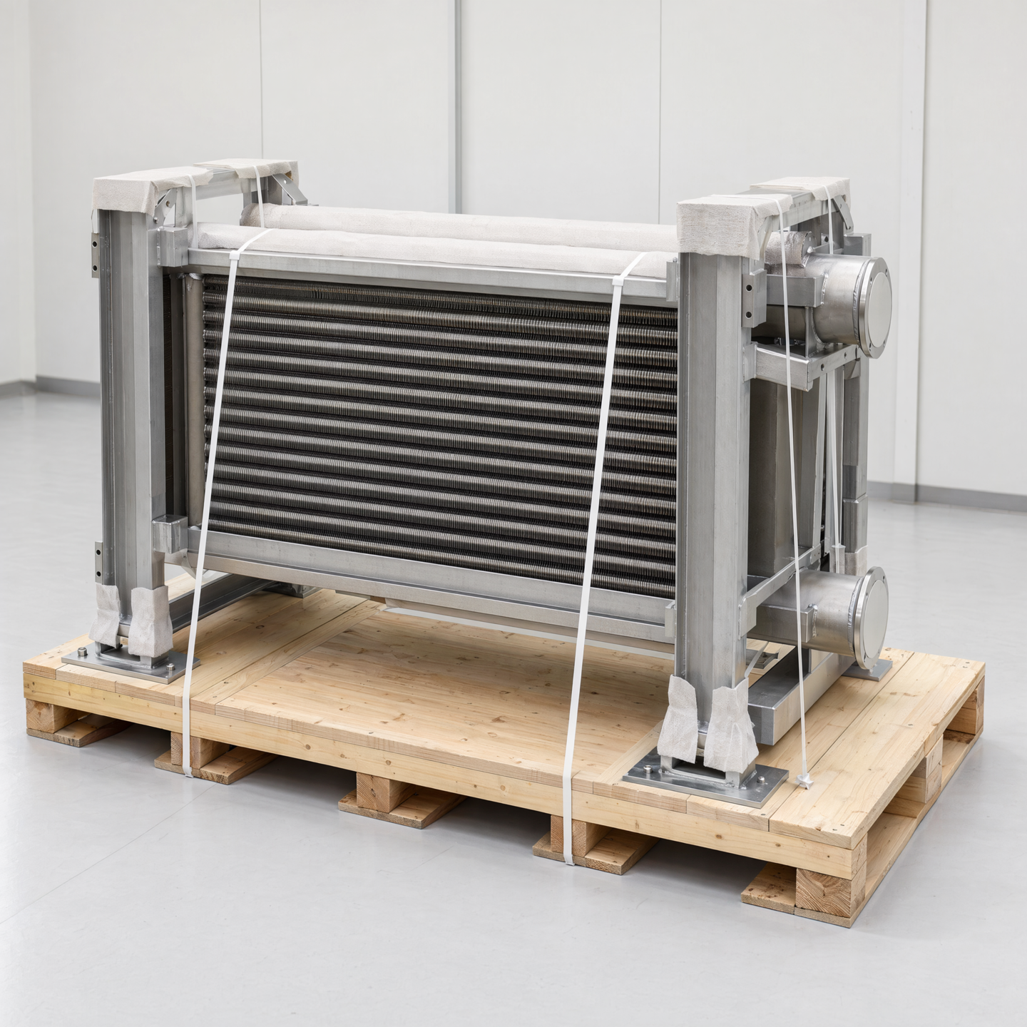

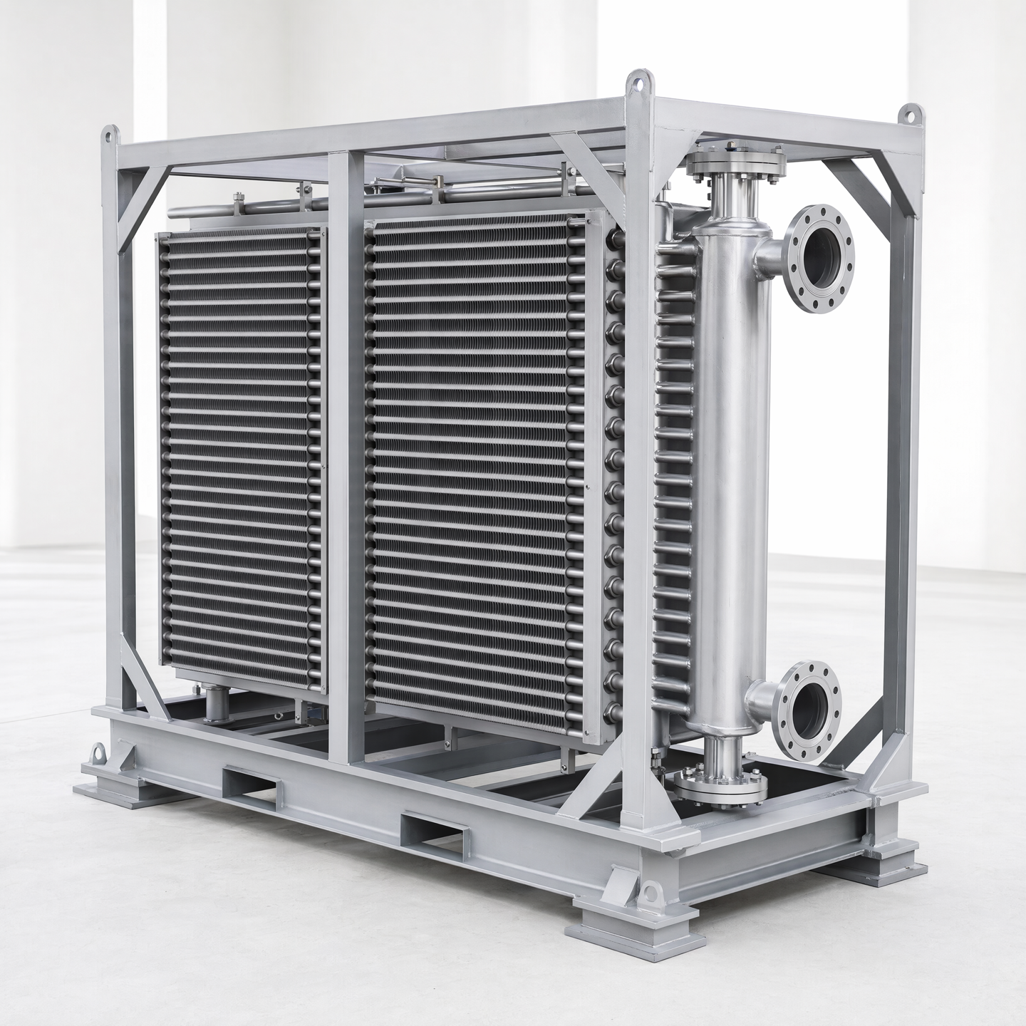
Large heat-exchanger frames are often easier to fabricate as one coordinated assembly than to transport as one piece. That difference creates a design and documentation problem. Once a frame is divided for delivery, the project has several temporary products: the shop assembly before separation, the individual shipping modules, the protected transport loads, and the reassembled site condition. Each state needs an identity, defined supports, permitted movements and measurable acceptance points. A note that simply says "split for shipping" does not provide that control.
This guide addresses fabrication and handoff planning. The customer owns thermal duty, heat-transfer design, overall equipment arrangement, service requirements, design loads, structural adequacy, installation constraints, site access and approval of the final split concept. StelTherm may review how an approved design can be divided, detailed, match-marked, trial assembled, protected and documented for local reassembly. It does not select the exchanger, calculate structural or transport loads, approve lifting engineering, direct site work, or guarantee thermal performance.
No universal module size, joint form, tolerance, bolt grade, lifting point, packing method or field sequence is prescribed here. Those decisions depend on the responsible design, route survey, carrier, site method, governing requirements and contracted scope. The practical objective is narrower: before release, make every shipping state explicit enough that fabrication and site teams do not have to recover the original geometry from memory.
Treat the shipping split as a controlled product boundary
Start with a responsibility map. Name who approves the split, who checks the transport envelope, who designs temporary restraints, who supplies fasteners and seals, who removes transport steel, who performs local joining, and who accepts the reassembled condition. Mark each activity as included, excluded, customer-owned, site-contractor-owned or subject to later agreement. If a party is not appointed yet, record the open responsibility instead of writing an instruction to an unknown installer.
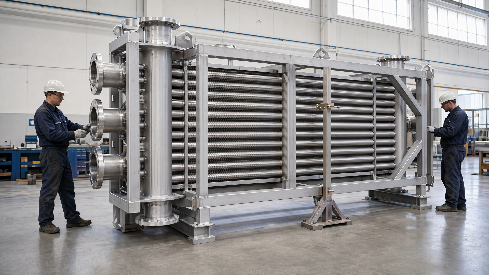
The drawing set should distinguish the design assembly from every temporary delivery state. Give the complete equipment one parent identifier and each module, loose item, temporary member and packing unit a child identifier. State whether the modules are separated after a full trial assembly, fabricated independently against shared tooling, or brought together only at site. The selected route changes what the shop can verify before dispatch and what evidence the field team needs.
Keep design authority visible when fabrication proposals are developed. Moving a split away from a difficult weld, adding a bolted splice, creating a removable brace or changing a frame member to improve access can affect stiffness, load paths, thermal growth, piping interfaces, coating continuity and service access. A manufacturability proposal should identify those affected relationships and return the decision to the responsible designer. Silence is not approval, and a convenient shipping module is not automatically an acceptable operating structure.
Define the contractual delivery point for each module. "Ex works module," "loaded transport unit," "delivered module," and "reassembled equipment" are different acceptance states. State which surfaces, protections, records and loose items must be present at each handoff. This prevents shop completion from being confused with site completion and keeps local activities from being represented as factory evidence.
Fix the transport and site basis before drawing the split
A useful split study starts with constraints, not with a convenient line through the model. Record the route-survey envelope supplied for the project, including permitted length, width, height, mass, support arrangement and any center-of-gravity or lifting information owned by the transport plan. Record doorways, laydown areas, crane approach, turning space, floor restrictions and the orientation in which each module is expected to enter the site. If those inputs are provisional, label them provisional and prevent premature drawing release.
Account for the complete shipping load rather than the bare product envelope. Skids, saddles, weather protection, protruding connections, temporary bracing, lifting lugs, shock-sensitive instruments, covers and required handling clearances all consume space. A module that fits the nominal carrier dimensions in CAD may not fit after protection is added. Conversely, designing packaging before the support and lift strategy is known can place timber, steel or straps where inspection, drainage or lifting access is required.
Show the planned transport orientation and distinguish it from the operating orientation. A frame moved on its side can impose temporary support conditions that do not exist in service. The responsible engineer must define or approve the temporary load case and restraint concept. The fabrication package should then identify the approved support points, prohibited contact zones and temporary members, without inventing unverified load capacities.
ISO 780:2015 is officially titled Packaging - Distribution packaging - Graphical symbols for handling and storage of packages [4]. The official record is cited only to identify that normative subject. It does not define a project lifting method, certify a package or replace carrier instructions. If the standard applies, the project must identify the edition and complete marking requirements, and the handling plan must remain consistent with the actual module.
Choose a split that works through fabrication, transport and reassembly
Evaluate each candidate split against the complete route. The interface must be fabricable and inspectable in the shop, accessible for controlled separation, protected during transport, reachable during site alignment, and suitable for the approved final connection. Check what crosses the split: frame members, braces, tube supports, piping, drains, instrument routes, insulation, cladding, platforms, guards and removable service components. A split that appears clean in one structural view may create multiple unresolved boundaries elsewhere.
Avoid using the split to conceal a design conflict. If the final operating structure requires continuity across a member, the approved splice must preserve the responsible designer's intent. If piping or headers cross the boundary, the drawings must identify their own field interfaces and responsibilities. If a component cannot tolerate field joining, transport exposure or local adjustment, its delivery state may need to change. These are design decisions, not matters for a general fabrication note.
Prefer interfaces that can be observed and accessed in the intended sequence. Provide space for locating devices, fastener installation, tools, joining access, inspection and later removal of temporary hardware. Check whether one module blocks access to the next joint. Check whether platforms, guards or cladding must remain off until the structure is accepted. Define the closing sequence while the team can still alter the module boundary, rather than after all joints have been released.
Plan how shop assembly will represent the site condition. If the entire frame is trial assembled, state which connections are completed, which are temporary, and which measurements establish the baseline before separation. If modules are verified independently, explain how their interface features are related to common references. If a surrogate fixture represents an adjoining module, identify the fixture, its calibration or verification status where required, and the limitations of the evidence it provides.
Build a reassembly datum scheme that survives separation
Reassembly datums should originate from functional installation or equipment references, not from accidental edges of transport steel. Identify the primary reference that establishes the rebuilt frame in space, the secondary reference that controls direction, and the tertiary reference that closes the remaining movement, using the project's approved geometrical-product-specification approach. Then show how each module carries accessible targets or features that preserve a traceable relationship to those references.
ISO 5459:2024 addresses datums and datum systems in geometrical product specifications [6]. ISO 129-1:2018 addresses the presentation of dimensions and tolerances [5]. These official records are cited for their public titles and normative subjects only. This article does not reproduce their requirements or claim conformity. The responsible design authority must provide the applicable editions, tolerance scheme and project interpretation.
Do not rely on painted match marks as the only means of locating a critical interface. Match marks communicate identity and orientation; they do not by themselves constrain translation, rotation or elevation. The approved design may use machined faces, fitted features, controlled holes, removable pins, reference pads, survey targets or another suitable locating method. The drawing should distinguish locating features from fastening features and should state which items are temporary, reusable or removed after acceptance.
Protect the datum chain from fabrication through delivery. If a datum pad is coated, covered, used as a skid contact or placed behind a transport brace, the intended field measurement may become unreliable or inaccessible. Show permitted surface treatment, masking or protection and when it is removed. Where a reference target is detachable, control its identity and installation condition. Where a target can be damaged, define how its condition is checked before dispatch and again before reassembly.
Large-scale measurement is a recognized metrology problem, but published methods do not create a project tolerance. Estler and colleagues reviewed developments in large-scale metrology [1], and Peggs and colleagues later surveyed large-scale dimensional metrology technologies and applications [2]. Their relevance here is procedural: measurement volume, environment, access, uncertainty and reference realization should be considered when selecting a verification method. The customer-approved acceptance values and measurement plan still govern the order.
Detail every joint, locator and temporary member
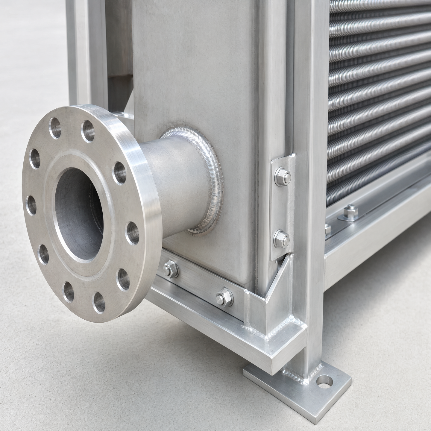
Create an interface schedule for all split locations. For each interface, list the adjoining module identifiers, drawing detail, connection type, locating features, fasteners or approved joining requirements, access direction, temporary hardware, surface protection, inspection stage and acceptance owner. Cross-reference the structural, piping, platform, cladding and electrical documents that cross the same boundary. One schedule exposes omissions that can remain hidden across separate discipline drawings.
For bolted interfaces, the responsible documents should define the approved fastener specification, quantity, installation condition, hole or slot intent, washer arrangement, locking method where required, tightening basis and treatment of unused transport holes. For welded field interfaces, they should define the approved joint, preparation, access, process and inspection requirements through the qualified project route. This guide supplies none of those values. Its purpose is to prevent a split symbol from standing in for a complete joint definition.
Separate alignment aids from permanent load-carrying details. A draw bolt, temporary strongback, jack point, drift allowance, guide plate or removable pin may help bring modules together, but it must have a defined purpose and removal state. Do not let an assembly aid become an unreviewed permanent member. Likewise, do not use final fasteners to force a large geometric mismatch unless the approved procedure explicitly permits the action and the responsible authority has assessed the consequences.
Qin and colleagues reported a robotic method for guidance and alignment of large-scale objects [3]. That research does not prescribe manual frame assembly or prove a StelTherm process. Its bounded relevance is that large-object assembly benefits from an explicit relationship between measured pose, guidance and final alignment; the field method should not depend on vague visual alignment when controlled interfaces are required.
Keep modules, loose parts and records connected
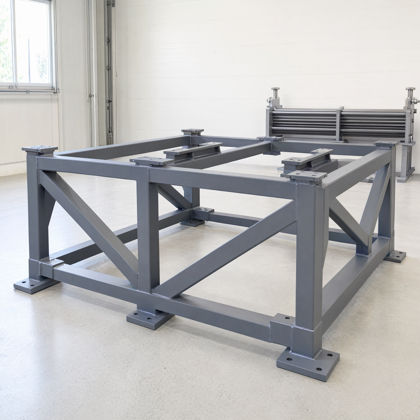
Assign a stable identifier to each shipping module and repeat it on the module drawing, packing list, physical tag, inspection record and reassembly plan. Use orientation marks that state the viewing basis: north or project axis, inlet side, module sequence, top, or another unambiguous customer reference. Avoid informal labels such as "left section" unless the drawing defines the viewpoint. Mirrored modules and similar braces are especially vulnerable to reversal.
Control loose parts as a kit. Fasteners, shims, pins, covers, seals, removable handrails, small spools, instrument brackets and touch-up materials should have part identifiers, quantities, interface destinations and package locations. Where a loose part is fitted to one specific interface, preserve that relationship. Where parts are interchangeable, say so only when the controlled definition supports it. A crate marked "site items" is not an adequate installation record.
Record shop-fit evidence before separation. Photographs may support orientation and condition, but they do not replace controlled dimensions or inspection records. Capture the approved interface characteristics, module positions, installed temporary members and any agreed shims or fitted items. Record deviations through the project nonconformance or approval route. The field team should receive the accepted as-shipped condition, not an idealized drawing that ignores authorized changes.
Design packing and handling around the reassembly plan
Each module needs a handling drawing or controlled instruction that identifies its shipping orientation, approved lift or support points, center-of-gravity information supplied by the responsible plan, temporary bracing, prohibited contact areas and protection boundaries. Keep slings, forks, chains, straps and skid members away from fins, prepared connections, sealing faces, datum targets and unsupported projections. If a handling feature is valid only in one product state, say when it is installed and removed.
Protect interfaces so that reassembly work does not begin with repair. Use approved covers, caps, barriers or packing details for machined faces, flange faces, prepared weld ends, locating pins, threaded features and exposed measurement targets. Define drainage and ventilation where packaging can trap water. Identify preservation that must be removed before assembly and the party responsible for disposal or return of reusable transport items.
Arrange the load and packing list in the sequence needed at site when practical. The first required alignment hardware should not be buried below a module that cannot be moved yet. Put lifting instructions, packing lists, interface schedules and controlled reassembly documents in a known protected location and provide the agreed digital record separately. If a crate is opened for customs or inspection, define how completeness and protection are restored.
Write a reassembly sequence that preserves access and authority
A useful site sequence begins with prerequisites: approved foundation or support condition, verified laydown area, available lifting method, correct modules and kits, released drawings, named supervision and accepted environmental or safety controls. It then states the intended module order, temporary support state, initial locating method, connection sequence, intermediate checks, removal of transport members and final verification. Hold points should identify who may authorize continuation.
Keep the sequence compatible with access. A module placed too early can block survey lines, fastener installation, joining, coating repair or inspection. Temporary platforms may be needed before permanent platforms can be installed. Cladding and insulation may need to remain open until structural and piping interfaces are accepted. The drawings should make those dependencies visible rather than forcing the site team to dismantle finished work.
Define how departures from the planned fit are handled. The field team should not enlarge holes, cut braces, discard shims, force flanges, heat members or change a joint without the authorized project route. The reassembly instruction should name the stop condition, evidence to collect, responsible reviewer and document used to approve a disposition. This protects both geometry and responsibility when actual site conditions differ from the basis.
Close temporary states deliberately. Identify all shipping braces, lifting attachments, locating aids, covers, blanking items and temporary supports. For each, state whether it remains, is removed, is replaced, or is returned. Mark any resulting surface treatment, closure or inspection requirement. A final walkdown should reconcile the temporary-item register so that transport hardware is neither left in service unintentionally nor removed when it is part of the approved assembly.
Verify the rebuilt frame from functional references
Agree the verification plan before shop separation. Identify the characteristics checked on the complete shop assembly, on individual modules after separation, on receipt at site, during initial positioning, after permanent connection and at final handoff. Each check should name the datum system, product state, method, acceptance source, record and decision owner. Do not transfer a shop result to the site state when transport or reassembly can alter the characteristic.
Measure the interfaces that protect installation and connected equipment: approved support positions, mounting references, header or nozzle relationships, frame geometry, platform boundaries, service clearances and other customer-defined points. Do not inflate the report with dimensions that have no acceptance role. Conversely, do not omit a hidden relationship merely because it is difficult to reach after closure; schedule it at an earlier hold point and retain its traceability.
Account for measurement conditions. Temperature, floor or foundation stability, instrument setup, line of sight, target accessibility and module restraint can affect a large-frame result. The responsible measurement plan should state the conditions and uncertainty treatment required for the decision. A high-resolution instrument does not compensate for an unstable reference, an inaccessible target or a tolerance whose interpretation was never agreed.

Finish with a reassembly dossier linked to the parent equipment identity. It can include the approved module drawings, revision register, packing lists, temporary-item register, shop-fit records, as-shipped deviations, receipt condition, site hold-point records, interface verification and authorized dispositions. The dossier should show what was actually assembled and accepted without claiming that a fabrication record proves structural, code or thermal performance beyond its defined scope.
Shipping-split release checklist
| Release question | What the controlled package should identify |
|---|---|
| What is being shipped? | Parent equipment, module boundaries, delivery states, module identifiers, mass and envelope data supplied by the approved plan. |
| Why is each split here? | Transport and site basis, affected systems, approved structural or design decision, fabrication and access consequences. |
| How is geometry recovered? | Functional datum system, module targets, locating features, match marks, baseline shop-fit measurements and site method. |
| How is each joint completed? | Interface schedule, approved connection detail, access, hardware or joining requirements, sequence and inspection hold points. |
| What travels separately? | Loose-part kits, fitted-item relationships, temporary members, covers, documents and exact packing locations. |
| How is the rebuilt state accepted? | Characteristics, product state, datum, method, acceptance source, record, authority and dossier handoff. |
Release the split package only when the design authority, fabricator, transport planner and responsible site party have a consistent basis for the work within their scopes. A complete package does not eliminate field judgment, but it prevents fundamental product identity, geometry and responsibility from being rediscovered beside an open crate.
References
- W. T. Estler, K. L. Edmundson, G. N. Peggs and D. H. Parker, "Large-Scale Metrology - An Update," CIRP Annals, 2002. https://doi.org/10.1016/S0007-8506(07)61702-8
- G. N. Peggs, P. G. Maropoulos, E. B. Hughes, A. B. Forbes, S. Robson, M. Ziebart and B. Muralikrishnan, "Recent developments in large-scale dimensional metrology," Proceedings of the Institution of Mechanical Engineers, Part B: Journal of Engineering Manufacture, 2009. https://doi.org/10.1243/09544054JEM1284
- Z. Qin, P. Wang, J. Sun, J. Lu and H. Qiao, "Precise Robotic Assembly for Large-Scale Objects Based on Automatic Guidance and Alignment," IEEE Transactions on Instrumentation and Measurement, 2016. https://doi.org/10.1109/TIM.2016.2526738
- ISO, "ISO 780:2015 - Packaging - Distribution packaging - Graphical symbols for handling and storage of packages." Official ISO record.
- ISO, "ISO 129-1:2018 - Technical product documentation (TPD) - Presentation of dimensions and tolerances - Part 1: General principles." Official ISO record.
- ISO, "ISO 5459:2024 - Geometrical product specifications (GPS) - Geometrical tolerancing - Datums and datum systems." Official ISO record.